Tuesday, 2 October 2018

Baguley-Drewry Project Pt.3

Continued from Part 2.


08/03/18
Cab interior parts painted. No idea if these are prototypically accurate, and at this point I don't want to know. Good enough for once. As an experiment, after painting the black gauge faces, I tried scoring them with a knife to see if I could reveal the silver underneath, to represent the markings & needles. I'm amazed it worked. Should've done the same with the white gauges, being a more visible colour..

The seats are a bit crude but again, they'll do - you won't really see 'em. The timber effect was done by drybrushing washes over a tan basecoat, along with some scoring of the plastic before painting. The solvent-based glue has caused the seat tops to warp a bit, as when the solvent evaporates and the plastic re-hardens, the plastic shinks a bit. I'll try to straighten them.
The floor has yet to be weathered.

27/03/18
Attempts at fixing the paint on the bonnet are not going well at all.

After filling in the nearby panel lines with repeated sanding and recoating, and trying to scrape them out resulting in the paint just chipping away from the surrounding areas, I realised I'd have to strip everything back to bare plastic and start from scratch.

But can spray enamel be stripped without harming the plastic underneath? Some research suggested that soaking in rubbing alcohol might work.

It shouldn't harm the plastic shell, I already had a small plastic container with a rubber-sealed lid, filled with alcohol, to use as a stripping bath for removing factory paint from plastic HO parts. But that's acrylic stuff and "cool" lacquers..


So I stood the bodyshell in the bath overnight as an experiment.
Alcohol does work on enamel, but very slowly.
I'm gonna need a bigger bath and a lot of alcohol to strip this thing. Fortunately, I buy a 5L bulk bottle of alcohol every two years or so. So it works out around $5.40 a litre which isn't half bad. I could use meths which is only $3.50 a litre, but it's stronger stuff, and may harm the plastic.


A toothbrush took off the first layer of white, with the yellow underneath requring fingernails to remove - it needs more soaking. This is gonna take a long time.

I've no more photos of the stripping, but it took nine days to strip the bodyshell, one side at a time, in a larger tray of alcohol. While soaking, an old shirt was draped over the tray to help limit evaporation. The shell was removed four times so I could pour the alcohol through a piece of stocking, to filter out the paint particles.

Even so, the alcohol needed replacing twice, so I wound up using 2.5L of it. A plastic brush bit in the dremel was used to get into the corners.


04/05/18
The bodyshell is fucking finally painted.
Lesson learned: Don't allow yourself to spray in subpar lighting.
Why ever I let myself do it in poor light is nothing short of ludicrous.
I used Tamiya masking tape, very carefully applied, when spraying black over the yellow. Good stuff, highly recommend it.
Don't forget to spray a light coat of your base colour over the masked line and allow to thoroughly dry, before painting the next colour. It stops the new colour from bleeding under the tape.

The Darjeeling-Himalayan-type couplings from IP Engineering however, need a lot of cleanup. I've seen worse castings though, and these are certainly usable. Besides, at £4.50GBP - $8AUD for the pair, I'm not complaining.

One issue with these is that the rivet details aren't very well-formed, and they're not even in alignment with eachother. As I'm modelling a late 60's-mid 70's vintage loco, I don't want rivets anyway - A welded appearance is more appropriate in this case. Were I modelling something earlier, I'd still remove these lumps, and drill holes in their place, for HO track nails or dressmaker's pins to be glued in, their heads looking much better as rivets. The hole in the top for the hook will need drilling out, as it's not all the way through.

Now, unlike most of IP's couplings, it turns out these don't have an M3 stud embedded in the backside for a strong mount to the chassis. I've glued couplings onto wagons before, and it's always failed on me. These have a lot more surface area though, which I'm sure is fine when gluing them to a wagon chassis.
But this loco is expected to see use towing steam locos (and their trains) back to a siding after they run out of gas. So these couplings are gonna need to be properly mounted.
I decided to use M3 hex bolts & nuts to sandwich the couplings and headstocks together.


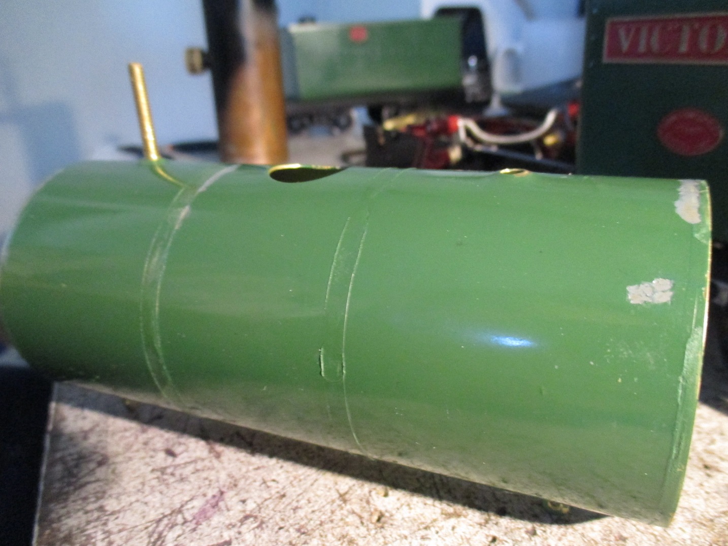
After removing the casting lines and rivet detail, I noticed the hollowed-out section inside both castings had a nice big 'wedge' of whitemetal, (reinforcing?) where I needed a flat area for the bolt head to seat..
 
..So removing the HSS tool in my Advance lathe's toolpost, I clamped a coupling in the toolpost and brought it up to the right height with whatever shims were around, making sure the casting was perpendicular to the chuck.
A small endmill was thrown in the chuck, and 2 minutes later I had a nice flat area for the bolt head to sit. This was repeated with the second coupling. The area under the hook mount was also milled flat, in case I need to add a reinforcing plate, as there's very little material to keep the hook in place.

Seems good, if a bit high for a sugarcane loco. Most cane railway couplings are pretty low-slung even today, due to the small 13" wheels most cane wagons have always rode on.
Most of my wagon couplings are around the standard 16mm scale height of 25mm.
As I'm modelling a fictional 3' gauge line, I figure I can get away with it.

I find the standard shape of coupling hook is too difficult to couple/uncouple, (despite using pliers) so I bend them over a bit. (left) In theory, this makes them more suseptible to coming uncoupled with rough track or rough shunting, but I've had no issues so far.


Looks ok, just needs blackening and trimming to size prior to guing in with JB Weld. As mentioned before, I am concerned about the lack of material in the hook's whitemetal mount, but will see how it goes in operation before doing anything further with it.

After a coat of etch and filler primers, the buffer face is cleaned with thinners. I will do the same after the red topcoat dries. By doing it now however, it'll leave an imprint under the red topcoat, so I can get a better idea of where to remove the red paint, without making an outline of primer visible around it.

This trick helps, but you will end up with a few spots of primer. To fix that, spray (or brush) a tiny amount of  matt black paint onto a thumb-sized section of rag, then dip the painty section of rag in thinners. The wet patch of rag is then stretched over the tip of your index finger, and dabbed sparingly over the bare metal area of the buffer face, disguising the primer patches and takeing away the whitemetal's shine.
This could be repeated with a rusty brown colour, but I've not yet tried that, and can't say for sure how it'd look. I'd bet it looks quite good, but keep forgetting to give it a go.

Further weathering will come later.

15/05/18
Now that the body's painted, I can finally get the electrickery out of the way and fit the interior. Here, five wires have been run to both headlights and the strobe light. I've used the spare hookup wire from HO point motors. Very small stuff, and utterly brilliant for this sort of wiring. I've got enough for this job, but my supply's running low. Will have to find a place that sells it in rolls. Shops don't seem to have it..


The driver's desk and centre-console-thingy were made to have the head/strobe lights' wiring run through them. They still needed a little opening out to fit the five wires through. Some cheap ABS channel I have lying around was ideal to cover it all up. A bit overscale, but it's not that noticeable.

Working out routing for the head & strobe lights, around the existing electrickery in the bonnet.
I wanted to make it so that everything is connected with one plug to the chassis. This makes it easy to separate the chassis from the body, 'cause it will have to happen at some point.
Annoyingly, I couldn't find a 7-pin plug locally. The best I could find was a '6er. So the battery has it's own connector. This at least allows the battery pack to be removed entirely, should I ever need to.

The thinned section of bonnet wall to the right, was done months ago with the dremel, to make room for the headlight switch body.


24/05/18
I'd found a box of figures on a Farcebook garden railway group. None of them are particularly "Australian-looking", and I can't be fucked to mess around with putty and learn to make them look right, so this guy'll do. Maybe he's an Ex-Queensland Government Railways driver, of the fastidious type, showing up to drive cane trains dressed like he's driving the Sunshine Express up North. I've given him a new coat of paint, a little weathering with washes, and I'll call him "Luigi"..

01/06/18
After fitting the interior detailing, and the satin clearcoating of the body had cured, the loco was reassembled for a very quick test on the floor.
All seems surprisingly good. Only issues are a noticeable rod clank (more of an annoying 'tink' with every revolution of the wheels) that's appeared out of nowhere, and it had a tendency to 'waddle' a bit on these 2' radius Nequida curves. That's fine, because when we find a new place to live soon, the new line will have 4' raduis, minimum.

The clanking might go away after I actually lubricate the rods. The rods will need touchup painting soon, so I'd rather keep oil away from them until literally everything else is complete. As the rods just flap around for looks, running them dry for a 2-minute test run is fine by me. The main bearings have been oiled, though.
Apologies for the poor light in the living room.

04/06/18
I realised even in the 70's, cane diesels had fire extinguishers fitted, so I started thinking about how to make one in a suitable scale. After comparing the standard extinguisher sizes on Google with photos of locos, I settled on fitting the 12kg model. The dimensions were found and scaled down to 1:20.

 Mostly machined from scrap aluminium, with the tank's radius formed with files on the lathe. The pin where the hose mounts, and the pivot pin are dressmaker's pins. The handle is folded up from some scrap steel. Shockproof superglue locks everything in place.

A very poor view of the completed interior shows there's hardly any room for the seats. I considered leaving them out, but wound up squeezing them in.

27/06/18
A 'base' for the strobe light was machined from aluminium. Not yet sure if I'll paint it. The windows have finally had their old glue scraped from the mating surfaces, and glued back into place, sealing the cab up again.

17/07/18
Final touchup of the paintwork has been causing headaches for over a month.
Normally, I spray whatever colour of paint I've used, into the can's lid, and use a small brush to to apply it. The can I used to spray the 'motion' with, was about 2 years old and getting empty. It ran out on another project, long after having sprayed these parts.

By the time these parts had eventually hardened, I reassembled them. I bought a new can of paint of the same brand/colour, and after a thorough shake, proceeded to start touching up. Somehow, this stuff turned out to be several shades lighter, so I let it sit for a week. Then another week. Then another. By the time it had hardened, the colour hadn't changed a bit. Fuck. So I tried some of the same colour, that came in a tin rather than an aerosol can - still a lighter shade. Okay, now I know the old spray can was at fault.

Que three weeks of procrastinating starting the annoying and time-consuming trial-and-error process of matching the colour in a spare paint jar. As the camera doesn't pick up the different shades too well, I've partially de-saturated the photo in the computer, to make the differences more visible. At this point, I'm having to test the colours directly on the motion (because it comes out differently on coffee stirrers, and wastes valuable material) - which once I finally get the colour right, was going to have to be airbrushed over the trial-and-error touchup patches anyway. This also requires the parts to be removed from the loco.

Of course it's obvious: I should've taken the fucking things off and resprayed them from the get-go. What's more, the headstocks and couplings will have to come off for respraying so they'll match, too.

21/07/18
One thing that's always bothered me with this loco, is the 1.5mm gap between the footplate and the bonnet, halfway up the length of the loco. I'd checked the plastic bodyshell and it's not deformed - it's perfectly straight. The 3mm steel footplate however, somehow has a 1.5mm bow in it.
Looking back at the photos from when the loco arrived here, it's always had that gap. As I'd half-dismantled the chassis to repaint the red bits, I figured I'd better fix this footplate too.

22/07/18
All motion parts have been stripped to bare metal and etch primed. The speckled appearance of the primer here is because it's a new can and I'd not shaken it quite enough. These were lightly rubbed back and re-resprayed.

When fitting the couplings, I'd put a little shockproof superglue behind the couplings to keep them from swiveling on their mounting bolts. This had to be scraped off before cleaning and sticking to the timber with blu-tac. They're on the same bit of timber as the cranks/pins so they copped a bit of overspray. (more like splatter, I should swap out the nozzle on the etch primer)

The footplate took an absolute fuckload of club-hammer-beating to straighten it, and even then it's still not as good as I'd like. Steel isn't normally this tough, in my experience. Belting it with a hammer of course ruined the finish, so it was sanded back with emery, cleaned with meths and primed along with the motion parts.

I have no idea how something so tough could've gotten so deformed. It certainly hadn't had a whole lot of use before I got it, and there was no other damage to speak of. Despite being fitted with extra track pickups, the chassis looked to never had been disassembled, as the paint on the bolts was untouched.
My only possible guess is it could've happened at Accucraft's factory. Maybe the footplate was somehow dropped from 2 floors up, or it might've just come out poorly. Considering Accucraft's relatively abysmal quality control, none of this would surprise me.

Another issue with having to do this, was some of my wiring was superglued to the underside of the footplate to keep it out of the running gear. I tried separating it with several blades, but the wires were stuck too well, and I had no choice but to destroy the wiring, tearing it away from the steel and scraping away the remains. So now I've gotta remake ¼ of the fucking wiring.

If I'm remaking ¼ of the wiring and repainting ⅔ of the chassis, I might as well remove the flange from the middle wheelset, so the loco will tolerate 2' curves - for if there's ever a time I can't avoid them.

I originally mounted the wheel in the 3-jaw self-centering chuck of my Advance lathe, by the retaining boss pressed into the back of the wheel. This was to save having to go dig an axle out of the loco's parts box.
It was amazing just how much the wheel wobbled, regardless of how I set it in the chuck, so I had to go find the axle. Thanks Accucraft, for reminding me why I'll never buy from you again.
Of course it's on me, for having broken that old vow when I bought this loco..
 

As I'm relatively new to machining, It's hard to know when the cutting tools need resharpening. Machining steel is a great way to find out your tools are blunt as fuck, so the surface finish isn't great. I don't have the energy to be anal about much of these things any more, so it'll do. I did resharpen my cutting tools though.

I'd forgotten I'd finished the fire extinguisher over a month ago. Excuse the oily fingerprints on the bracket's paint, that'll be rectified in due course. The bracket itself is made from ABS channel with a styrene strap and base. Beyond my parts box, I've no idea where the tiny rubber hose came from.

14/08/18
After repainting, drying for a couple days, then baking in the oven at 70 degrees C for a few hours, the red bits are finally done, and the chassis can go back together. The rods are stored safely until they're needed.

I noticed there's no means of preventing the main bearings from spinning in their mounts. Slow clap for Accucraft, once again. The bearings and their spaces in the frames, were thoroughly cleaned with meths before final reassembly. A touch of cyanoacrylate was applied to the side of each bearing, using a fine applicator. They don't need much, just enough to make sure they won't move in service.

04/09/18
After reassembling the loco and checking it ran ok on a loop of plastic track in the garage, I was able to get on with touching up the paint on the chassis. Here, the grey bits have been etch-primed.


07/09/18
After the primer's cured, some red paint was sprayed into it's lid.
Annoyingly, just as I was about to start painting, I realised I'd fitted the front headstock (with it's threaded hole for the strobe light battery retainer) at the rear of the loco. This needed to be swapped over.

As the body had to come off to access all the headstock screws, I figured I better make the dummy radiator before I forget again. I made it the same way as in the Malcolm Moore build.
The front of the Baguley's bonnet was measured, and those dimensions transferred to a piece of 1mm styrene, and cut out.

Some KS Bond contact cement was then smeared over the plastic. When you apply it this thin, it dries very quickly. I had to wipe it off and do it again because I stopped to take the photo.

Before all this, I'd found a suitable piece of rag - a sleeve from old cotton T-shirt. After cutting it so it would lay flat, a clean, undamaged spot was chosen and ironed smooth.
After re-gluing the styrene, it was pressed onto the fabric, being very careful to align it with the "grain" of the fabric. This way, I get a scale radiator texture, with nice vertical lines.

After letting it sit for ten minutes, the fabric was cut closely to the styrene with scissors. The edges were gone over with cyanoacrylate to stop them coming loose, then tidied up with a sharp knife.

Like in the Malcolm Moore, the "radiator" is removable to make any future resprays much easier.
In the 'Moore, it just slots in between the front of the bonnet, and the battery pack.
Here, I've blu-tacked it. After all that, I finally touched up the red paintwork. There's a couple bits needing a touch of black, then I can clean, weather and satin clearcoat the chassis to match the body finish.


That's it for part 3. Next one will see the loco finished.


Monday, 10 September 2018

Roundhouse Fowler "Victoria" Build Pt.5

Continued from Part 4.


10/05/18
It took a while to work out where exactly to route the wiring for the headlights on this loco. My crude-as-all-fuck circuit reference diagram in Microsoft Paint reflects my electrical expertise, such that it is..

I decided this loco was an ideal candidate to have a light in the ashpan, simulating the fire's glow for evening runs. I don't like LEDs, and avoid them where possible because:

1: The light's too focused for my liking, even if you diffuse the lens with sandpaper. This is a problem in firebox and interior lighting applications, where you need a strong radiant glow.

2: I won't go near those god-awful cool-white ones, with their blue tinge. It's the wrong colour, and reminds me of the modern world of needless electronics and over-complication - might as well paint my locos fluorescent yellow. I'd sooner have no working headlights than ones of the wrong colour. So whenever I must use LEDs, I use warm-white ones. I consider them passable for building lighting, but for a loco, the thing I spend most of the time looking directly at, you simply can't beat the look of a real incandescent bulb.
But each to their own, do what you like. The ramblings of a cranky purist should mean nothing to you.

3: Heat. LEDs stop working when they get hot, making them unsuitable for smokebox-mounted headlights, especially in hot countries like Australia. I know because I tried it on my Accucraft Ruby a few years back. Once they cool down, they work fine again.
The heat in the dummy ashpan of a gas-fired loco might not be too much for LEDs, but in this case, it's the least of reasons not to use them.

Besides, an LED in the ashpan would require not only a resistor, but also a bridge rectifier to work with both forward and reverse headlights - I think.. This is just more electrical complication that I don't need on a hot, oily loco that will occasionally get sprayed with degreaser and washed off under the garden hose.

I realise this is an inelegant setup, but it should work fine and more importantly, I can actually get my tiny mind around it. The drawing was cleaned up and labels added so it might make sense to the reader.


Now, I have a coach with two incandescent bulbs in it, running on a pair of rechargeable AAAs underneath. They must draw around 450mah each, because they deplete any AAAs in 25 minutes! That makes no sense. In theory, I'd get triple the running time from my rechargeable AAs.
I realised Victoria's tender had the same 2-cell AAA clip. I used up those old bulbs, and bought different ones, apparently rated at 60mah - what the old ones should be drawing.
As an insurance measure, I'm replacing the AAA clip with a AA clip.

I've also glued spacers underneath to keep the batteries off the tender floor, in case it's caught in the rain or gets water spilled in it.

03/06/18
A mate of mine is building an 0-6-0 coal-fired loco in 7/8ths scale, and drilled it's frames for dummy rivet detail. It looks great, and it's making me want to do the same on my frames, despite the enormous pain the the arse it would be to do. After weeks of thinking about it, I finally said "fuck it" and stripped the chassis down. It'll be painful to do, but once it's done, it'll be well worth the trouble.

The new coupling and eccentric rods have also arrived from Roundhouse..

..Along with a cast whitemetal generator, as fitted to their Darjeeling B class. I cleaned up the casting, drilled a mounting hole for the copper tube found in my metal scrap box, for the exhaust, in addition to drilling and tapping an M2 hole in the bottom of the casting, for the mounting bracket, which will need to be made from brass sheet..

Being a member of the museum owning the only surviving full-size Roundhouse Fowler, is very helpful in working out the details.
Despite the Roudhouse model's excellent running characteristics, there are a lot of missing or incorrect details. This is not a complaint, merely an observation. Besides, I'm not building a model of the real loco with it's exact details, but a freelance model of roughly the same design.
My preferred method of taking measurements is to lay the ruler or tape measure on the prototype, and photograph it from whatever positions I need. The measurements are then converted to my working scale using this excellent online converter.

 The frames' paint was removed wth paint stripper, followed by a wire wheel in the dremel. Permanent marker is used as marking fluid, and the hole locations are transferred from the converted prototype measurements and photos.
To locate the drill, I used a pin vice to start the holes exactly where I need them. More accurate than center-punching and doesn't work-harden or distort the frames. Far more time-consuming though.

26/06/18
After waiting for the supply of fifty 0.8mm drill bits to arrive, I started drilling. This took around 7 hours over a few days, as I had to go very gently on the drills.
Here, I've completed most of the drilling, and am test fitting a section of brass angle on the mid section of the frames. Looks okay, so I'll make it's twin and soft-solder them to the frames.

29/06/18
After cleaning up any errant solder, I drilled the last holes through the angle and frames. That makes 138 in all, blunting, broke or sometimes both, 30 drill bits. After test fitting a few dressmaker's pins, I realised the holes needed to be countersunk a little to allow the pins' heads to sit properly over the holes, so I did that with a 1.5mm bit, very carefully not to overdo it, which took another hour or so.

The original plan was to soft-solder these in. That didn't work out. It was impossible to not apply too much solder. JB Weld turned out to be a mess. So I glued them in with shockproof, high-temperature superglue.

Fairly happy with this result. Should look better under a coat of paint.

After the glue was allowed to fully cure, the pins were cut off with a cutting disk in the dremel.

06/07/18
The rivets still look a bit flat, instead of nice dome shaped heads, but they'll do. It's far better than the huge flat expanses of frames they were.

11/07/18
After reassembling the frames, the ashpan was installed permanently with JB Weld sealing the edges, ready to paint the inside and glue in some ash. If you're familiar with the Fowler, I know what you're thinking: "How will the boiler/cab mounting screw fit?" Well I mulled it over for a while, came up with some brilliant way of doing it, and promptly forgot it. I swear my memory's getting worse. Hopefully it'll come back to me before I decide to rip the ashpan off again to access the screw, or some other idiotic idea..


I filed a pair of grooves into the frame spacer, but of course forgot to make sure I'd done it on the right side. That countersunk hole in the middle, should be on the bottom side, for the boiler mounting screw. I rectified this by just countersinking the other side of the spacer.

Don't know why I thought it was a good idea to use flat black as a basecoat for the ashpan, long before final fitting. Not only is it the wrong colour, (should be rusty brown) but I knew it would be fitted and removed a bunch of times while tweaking things, causing the paint to flake off..

The bulbs were painted with a mix of Tamiya "Clear Yellow" with a little "Flat Red" mixed in, and wired up to their 4-pin connector. All seems to work thus far. The wire running off to the right are for the headlight.

A coat of Tamiya "Nato Brown" makes a proper base for weathering here..
When test fitting the cab, I noticed it wouldn't sit flat on the frames, now. After making certain it wasn't the wiring sticking up above the frames, I realised the frame spacer itself was causing the problem.
As I'd already glued the wires in with hi-temp superglue, I couldn't remove it and see if the tapped holes in the spacer were drilled off-centre. I suspect they were, because when this spacer was mounted the other way up, the cab sat on the frames just fine.

So I got the files out again, and carefully filed it down flush with the frames. The cab sits where it should again, and I can move onto the next job..

The ashpan was pre-wetted internally with isopropyl alcohol and real coal ash sprinkled in, trying to get some of the finer dust to stick to the walls, in an attempt to keep the colour fairly consistent. Another lighter spray with the alcohol, and a 50/50 outdoor PVA & water mixture was applied with a pipette.
I should've used water and dishwashing soap, but couldn't have been bothered to empty the alcohol sprayer and make some water/soap mix just for this. The alcohol wasnt ideal but it worked well enough, I think. The ashpan will get further weathering with powders, then carefully sealed.

After sitting the cab on it again, and hooking up the batteries in the tender, I noticed the ashpan light was too dim. Removing the cab for a good look at the bulbs revealed the alcohol had softened the paint on them, and allowed some ash to stick to and darken the bulbs' coating. I'll have to clean the paint off and redo them. Once again in hindsight, I should've known better.


After assembling the frames, I cheated a bit when making the mounting flanges on either end of the brake shaft. (only the visible outer ends were modelled)
I just used styrene sheet, as the frames at this end don't get anywhere near hot enough to seriously affect plastic. They were cut out and drilled prior to being JB Welded on, and drilled through the holes into the frames, before gluing in the dressmaking pin "bolt heads". These'll be painted during final touchup.


25/07/18
The bulbs were then cleaned and repainted, and the chassis surrounding the ashpan was masked with low-tack masking tape. The ashpan was then given some dusty weathering with pastels, ground up with a mortar and pestle, then applied with a dry paint brush.

26/07/18
So it turns out that real ash followed by pastels, then sealed in with a spray of Tamiya matt clear, makes for a very effective recreation of the horrible mess that is a fullsize ashpan. I got lucky with this trial-and-error. The camera doesent do it justice.

I'll need to be careful with the heat, water, oil and degreaser, then hopefully the ash effect will survive long-term. A coat of Humbrol matt clear enamel would seal it even better, now that I think of it.
As you can see, the bulbs were then cleaned with meths and repainted.

After some trial-and-error in tweaking the bulbs' positions, I got the effect I was after.
I can't claim the idea, of course, but I'd like to see more people doing this. It really compliments the effects of live steam.

There's a price for everything. If ever it seems there is no price for something, then the price is either inconsequential, or unknown. Well, that's what I've found, anyway.
With the ashpan JB Welded into the frames, mounting the cab and boiler is a pain in the arse, but I got it in the end. I had to fit the cab first and smokebox last - which is the opposite order to how it's done in the instructions.
The front headstock and cylinders had to come off, so the steampipe could be fitted after the cab/boiler.

I never really liked the standard reversing rod. It gets the job done, but it's not very realistic. I'm going to replace this with something more like the heavy forged things used on fullsize locos.

29/07/18
Speaking strictly as an individual, at the Woodford Railway Museum, there's no shortage of junk we'd be better off getting rid of. Here's a a "No Standing" sign I bought for $1 out of the scrap bin. It's 1.6mm mild steel. A dollar is far more than ANGRMS would get from the scrapman for it, and as far as sheet metal goes, it's way, way cheaper to buy, for someone chronically unemployed . Win-Win.
There's actually another 2 of these in with the scrap. I should probably buy those, too.

Before the day was out at Woodford, I stripped it with an angle grinder using a wire-wheel and flap disk. Pack up time was fast approaching, and in the end, I just took off any rust, and removed what I could of the paint. What's left appears to just be staining from the paint.

Anyway, it's perfect material for a a proper reversing rod.

A few hours of careful filing, bending and drilling later, I have something much better than that shitty bike spoke thing the kit came with.

The end of the rod was filed down to fit the reverser without modification. I've found the filed-down end to bend much more easily than I'd like. I should've removed the reverser entirely, and enlarged the hole the rod passes through, so the rod wouldn't have been filed down as much, leaving it stronger. This should be fine though, I just need to be gentle when fitting or removing it.

The hole in the cab front also had to be opened out with a file, to accommodate the new rod.

I machined a mild steel pivot pin for the front end. An M2 nut retains the rod.

02/08/18
At this point, I thought I'd make a start wiring up the front headlight. An offcut of wire from the demolition of my HO layout (moving house soon) was unwound, and three strands taken.

The strands were rewound with each other, soft soldered together and set aside for when I can complete the wiring.

I was not at all happy with the headlight reflectors I had tinned with soft solder. The front is obviously the most visible, and it was the worst. In normal lighting, it looked like it was painted black inside. I think the repeated immersions in citric acid, from when the smokebox had to be pickled after soldering the headlight bracket on, is what's affected the reflector so badly.

The rear headlight on the tender has had no such picklings, and is much better but still unacceptably dull. Both headlights need some attention. I've had an idea for a while, so I bit the bullet..

04/08/18
..And bought some of this stuff. It's a lacquer, used mainly in plastic modelmaking. Cars, planes, etc.
Nearly all paints labelled as "chrome" come out as a shiny silver at best. Not this stuff. It's nearly as good as real chrome plating. This little bottle cost about $16 AUD with another $10ish for post, from an Australian hobby shop selling through EvilBay. Expensive, but that'll last me many years.

It's very, very thin, to the point where there's no need to further thin it. Because it's so thin, it needs to be airbrushed on. Handpainting this stuff would like using water with glitter in it. It's a bit annoying though, having to buy a 1L tin of lacquer thinner, just for this lacquer I'd only use once every few years.

There's one other proper chrome paint to my knowledge, and it's called Spaz Stix. It comes in aerosol form. According to reviews, it's comparable to Alclad. I chose the latter because it would've been too risky trying to spray the inside of these headlights, now that they're fitted to the loco, without getting excess paint everythere. The airbrush is more hassle, but far more controllable.

A big part of what makes this stuff work so well, is that it must be applied over a gloss black enamel basecoat. So after handpainting etch primer and a coat of black inside the headlights and letting it dry for a few days, both ends of the loco were carefully masked off with the same Tamiya low-tack masking tape used around the ashpan.

When spraying, one thin coat (or two at most) is all that's required. After you're done, it's gonna look a bit like silver paint.The surface will appear sort of "dusty", from some particles of lacquer drying in the air before they even land on the part..

05/08/18
Being a lacquer, it dries very fast. 2 hours later, both reflectors were buffed very lightly with a clean cloth to remove the dried particles. At this point, the finish is fairly fragile, so some people spray an enamel clearcoat at this stage to protect it. This apparently dulls the finish a bit, though. I don't think extra protection's necessary for the relatively sheltered areas inside a headlight.

The surface isn't perfect, due to all the times the headlight's had to be retinned, but it's acceptable.
I think it'll hold up okay with the heat. I've heard of people using automotive lacquer on these locos without issue, and this headlight will be sealed once I fit the lens, so it'll only be heat for the Alclad to deal with.

The front isn't great if I'm honest, compared to the rear headlight. Both are still quite good enough, especially after the real glass lenses are fitted. Their reflectiveness will help obscure any imperfections in the reflectors. In the case of the rear headlight, I just sprayed over the bulb, then cleaned it off with a cotton bud dipped in thinners.

At this point, I dismantled the loco yet again (fuck's sake, Aaron, get it right the first fucking time for once) because the cladding's paint had not only been damaged when fitting and shaping the dummy pipework, but the paint sort of "mushroomed" around the boiler bands when the loco was steamed.
I was gonna have a go at scraping away the higher mushroomed bits of paint, then touch up the areas by hand, but quickly realised that would look like horseshit.

In hindsight, the paint on the cladding probably wasn't fully cured, so as the cladding heated up before the bands did, the bands effectively "bit" into the slightly-soft paint. I think this was exacerbated by the bands having sharp, square edges from when I filed away the etching lines along their sides. I never thought to bevel the inside edges slightly.

This time, I'll be certain the paint's fully cured, and bevel those inner edges.


By late that night, the old paint was removed, the cladding thoroughly cleaned, and a new coat of etch primer applied, dried and cured. This Supercheap Auto brand etch primer's pretty quick to dry, and a bake at 100°c for two hours finished it right quick.

30/08/18
Lightly beveling the inside edges with a sanding disk in the dremel.

02/09/18
The reversing rod, boiler cladding and motion are finally refitted. I'm getting sick to death of having this thing sit around unfinished, so I'll be fucking pissed if it winds up having to come apart again. The motion's got a lot of chipped paint, but once touched up it won't be visible.The valve timing is yet to be done.

The tiny 3-stand wire from earlier, was soldered onto the end of the wiring tube. (Middle pipe)
The idea is to use the tube itself, as one of the headlight wires running down the boiler, with the other wire (an insulated one) inside the tube. The wire running through the tube was recovered from the point motors on my recently-demolished HO layout. It's tiny stuff, and very hard to find, in my experience. Shops don't have it, and Evilbay only has it in bulk reels for $100AUD. I can't justify buying that much.

Both the bare 3-strand and insulated point motor wire were then routed into the headlight, with a sleeve of heat-shrink to hold the wires together. Makes for a fairly close-to-scale appearance. A small brass washer was annealed and formed to a dish shape, to conform to the curvature of the headlight. The wires and bulb were passed though the washer and inserted in the headlight, and the washer JB Welded over the wire hole in the light. Effectively works like a patch to reduce the diameter of hole to be filled in.
The hole was then sealed from the inside with hi-temperature cyanoacrylate, and the heat shrink - uh, shrunk.

Wiring this thing up was a fucking cow of a job. I broke the 3-strand off where it was soldered to the pipe, and had to resolder it, and damaged a bulb so had to replace it, but the job's finally done.

Getting the bulb in the right place (and holding it there while the glue dried) was also a pain, requiring a pair of pliers, which of course damaged the fragile Alclad inside the headlight. The white fume marks from the glue also marred the surface. So this headlight needs the Alclad process repeated. Fuck, why didn't I think of this earlier?


04/09/18
While I was touching up the Baguley diesel's paint, I figured I'd do some on the Fowler as well. Here, I've used etch primer, as most of the chipped or unpainted parts are non-ferrous anyway. The loco was cleaned and given a primer touchup as well.

The lubricator's paint was badly damaged many months ago, when I had to anneal the steam pipe with a butane torch.

The areas of black paint on the cream cab interior were there because I somehow missed those spots when masking to paint the floor. A few coats of cream applied with a brush, has left no trace of the errant black. I can now check "touch up cream paint" off the list.

That boiler identification plate is quite small and hard to read. I may yet get a larger one made..

For months, I've been forgetting to build the Stones generator. When I got it, I cleaned up the casting and found a suitable piece of copper tube to use as an exhaust. Here, I'm double-checking it'll fit the space I had in mind. It's snug, but good.

Now to make the bracket. I found this offcut of 0.5mm brass in my scrapbox. Permanent marker is used in lieu of engineer's blue. Using a try square, 6" steel ruler and a dull knife blade as the scribe itself, the sheet was marked out for cutting.

The tin snips I used (unsurprisingly) bent the brass, which was already pretty hard. So it needed annealing before I could hope to get it reasonably straight.

After double-checking, I still wasn't happy with the cut edges, so they were tweaked with a needle file in my 2" bench vice.

I forgot to photograph the process of marking out, drilling, bending, and punching dummy bolt heads in the bracket, so here's the generator ready for assembly. I don't have a small tube bender, so it was difficult to bend the top of the exhaust tube without crushing it. I got lucky this time, it came out okay.

07/09/18
I timed the motion last night. I prefer to do it on side at a time, with the other side's motion disconnected. That way, I know the other cylinder isn't working against the one I'm working on at any time.
I also do it with the loco in steam, rather than on compressed air, because I've found she behaves very differently on steam, than she does on air. Normally, a loco running on air will have it's valve events a little slower than it would on steam. Not this one, it seems. She's a totally different animal between steam and air. Very weird for a Roundhouse, but that's steam engines for ya.

With new coupling and eccentric rods, (and no excess slop or clanking) the job of timing was amazingly quick and painless, (other than the loco being hot) and the next evening, Victoria ran on track for the first time.
The timing still isn't quite right, but it's the best I can get it right now. As the motion wears in, I'll gain a bit more scope for adjustment, and get the timing much closer to perfect.

As the Anzac Creek line no longer exists, I set up a loop of Newqida plastic track just in front of the garage doorway, and set the loco running, while I make dogspikes for the next railway, on the bench grinder in the garage.

After clearing the cylinders of water, and unsurprisingly for a Roundhouse, I was nevertheless impressed by the way Victoria took to running. Not even bedded in, and already almost as smooth and powerful as my bedded-in, rebuilt, half-inch-cylindered, Accucraft Ruby.

I think the next article will be the last for this project, covering the little "buttoning up" jobs and further running in.

Part 6 Here