Continued from Part 4.
10/05/18
It took a while to work out where exactly to route the wiring for the headlights on this loco. My crude-as-all-fuck circuit reference diagram in Microsoft Paint reflects my electrical expertise, such that it is..
I decided this loco was an ideal candidate to have a light in the ashpan, simulating the fire's glow for evening runs. I don't like LEDs, and avoid them where possible because:
I decided this loco was an ideal candidate to have a light in the ashpan, simulating the fire's glow for evening runs. I don't like LEDs, and avoid them where possible because:
1: The light's too focused for my liking, even if you diffuse the lens with sandpaper. This is a problem in firebox and interior lighting applications, where you need a strong radiant glow.
2: I won't go near those god-awful cool-white ones, with their blue tinge. It's the wrong colour, and reminds me of the modern world of needless electronics and over-complication - might as well paint my locos fluorescent yellow. I'd sooner have no working headlights than ones of the wrong colour. So whenever I must use LEDs, I use warm-white ones. I consider them passable for building lighting, but for a loco, the thing I spend most of the time looking directly at, you simply can't beat the look of a real incandescent bulb.
But each to their own, do what you like. The ramblings of a cranky purist should mean nothing to you.
3: Heat. LEDs stop working when they get hot, making them unsuitable for smokebox-mounted headlights, especially in hot countries like Australia. I know because I tried it on my Accucraft Ruby a few years back. Once they cool down, they work fine again.
The heat in the dummy ashpan of a gas-fired loco might not be too much for LEDs, but in this case, it's the least of reasons not to use them.
Besides, an LED in the ashpan would require not only a resistor, but also a bridge rectifier to work with both forward and reverse headlights - I think.. This is just more electrical complication that I don't need on a hot, oily loco that will occasionally get sprayed with degreaser and washed off under the garden hose.
I realise this is an inelegant setup, but it should work fine and more importantly, I can actually get my tiny mind around it. The drawing was cleaned up and labels added so it might make sense to the reader.

Now, I have a coach with two incandescent bulbs in it, running on a pair of rechargeable AAAs underneath. They must draw around 450mah each, because they deplete any AAAs in 25 minutes! That makes no sense. In theory, I'd get triple the running time from my rechargeable AAs.
I realised Victoria's tender had the same 2-cell AAA clip. I used up those old bulbs, and bought different ones, apparently rated at 60mah - what the old ones should be drawing.
I realised Victoria's tender had the same 2-cell AAA clip. I used up those old bulbs, and bought different ones, apparently rated at 60mah - what the old ones should be drawing.
As an insurance measure, I'm replacing the AAA clip with a AA clip.
I've also glued spacers underneath to keep the batteries off the tender floor, in case it's caught in the rain or gets water spilled in it.

03/06/18
A mate of mine is building an 0-6-0 coal-fired loco in 7/8ths scale, and drilled it's frames for dummy rivet detail. It looks great, and it's making me want to do the same on my frames, despite the enormous pain the the arse it would be to do. After weeks of thinking about it, I finally said "fuck it" and stripped the chassis down. It'll be painful to do, but once it's done, it'll be well worth the trouble.
The new coupling and eccentric rods have also arrived from Roundhouse..
The new coupling and eccentric rods have also arrived from Roundhouse..

..Along with a cast whitemetal generator, as fitted to their Darjeeling B class. I cleaned up the casting, drilled a mounting hole for the copper tube found in my metal scrap box, for the exhaust, in addition to drilling and tapping an M2 hole in the bottom of the casting, for the mounting bracket, which will need to be made from brass sheet..

Being a member of the museum owning the only surviving full-size Roundhouse Fowler, is very helpful in working out the details.
Despite the Roudhouse model's excellent running characteristics, there are a lot of missing or incorrect details. This is not a complaint, merely an observation. Besides, I'm not building a model of the real loco with it's exact details, but a freelance model of roughly the same design.
My preferred method of taking measurements is to lay the ruler or tape measure on the prototype, and photograph it from whatever positions I need. The measurements are then converted to my working scale using this excellent online converter.
My preferred method of taking measurements is to lay the ruler or tape measure on the prototype, and photograph it from whatever positions I need. The measurements are then converted to my working scale using this excellent online converter.

The frames' paint was removed wth paint stripper, followed by a wire wheel in the dremel. Permanent marker is used as marking fluid, and the hole locations are transferred from the converted prototype measurements and photos.
To locate the drill, I used a pin vice to start the holes exactly where I need them. More accurate than center-punching and doesn't work-harden or distort the frames. Far more time-consuming though.

26/06/18
After waiting for the supply of fifty 0.8mm drill bits to arrive, I started drilling. This took around 7 hours over a few days, as I had to go very gently on the drills.
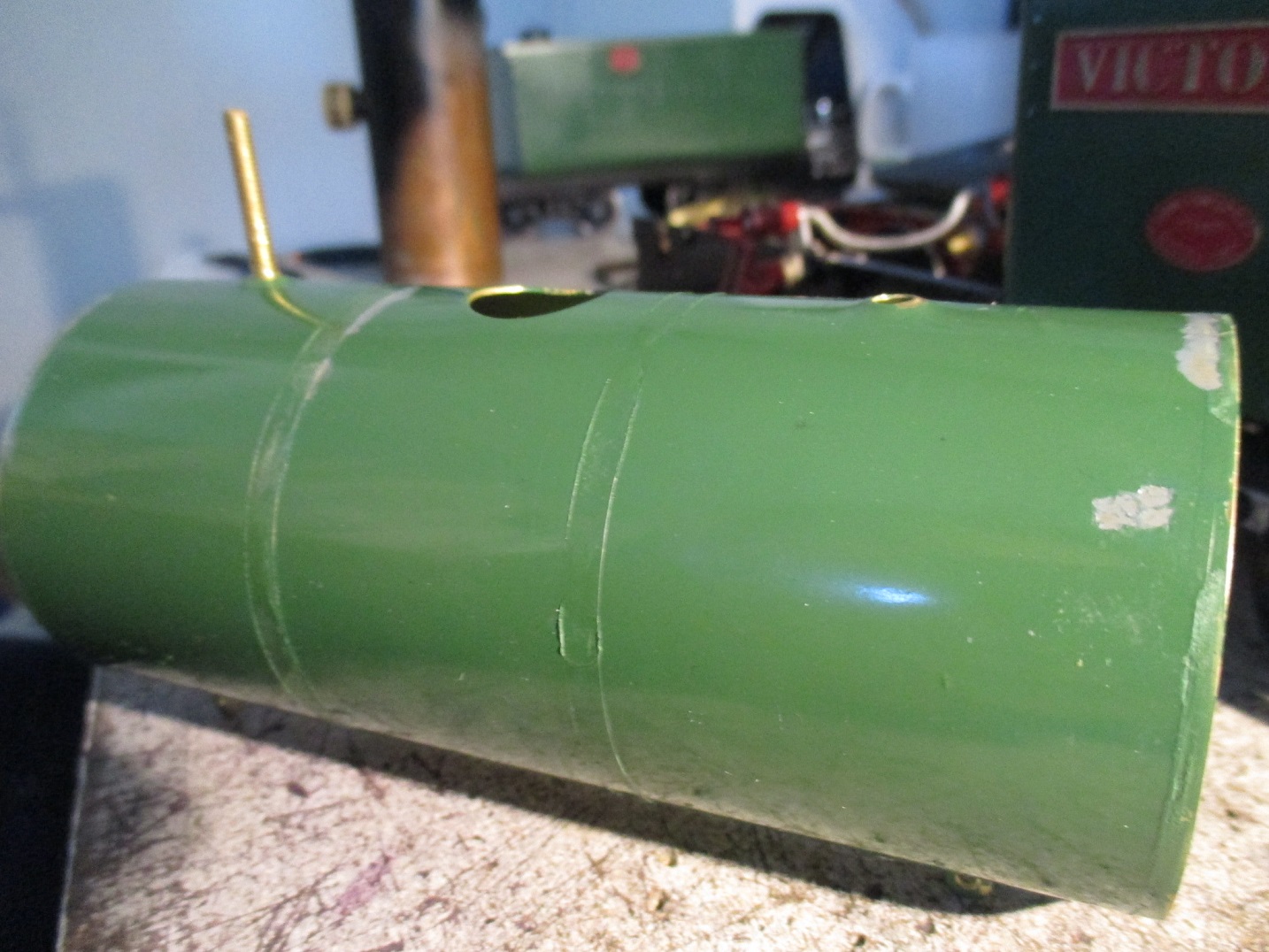
Here, I've completed most of the drilling, and am test fitting a section of brass angle on the mid section of the frames. Looks okay, so I'll make it's twin and soft-solder them to the frames.
Here, I've completed most of the drilling, and am test fitting a section of brass angle on the mid section of the frames. Looks okay, so I'll make it's twin and soft-solder them to the frames.

29/06/18
After cleaning up any errant solder, I drilled the last holes through the angle and frames. That makes 138 in all, blunting, broke or sometimes both, 30 drill bits. After test fitting a few dressmaker's pins, I realised the holes needed to be countersunk a little to allow the pins' heads to sit properly over the holes, so I did that with a 1.5mm bit, very carefully not to overdo it, which took another hour or so.

The original plan was to soft-solder these in. That didn't work out. It was impossible to not apply too much solder. JB Weld turned out to be a mess. So I glued them in with shockproof, high-temperature superglue.

Fairly happy with this result. Should look better under a coat of paint.

After the glue was allowed to fully cure, the pins were cut off with a cutting disk in the dremel.

06/07/18
The rivets still look a bit flat, instead of nice dome shaped heads, but they'll do. It's far better than the huge flat expanses of frames they were.

11/07/18
After reassembling the frames, the ashpan was installed permanently with JB Weld sealing the edges, ready to paint the inside and glue in some ash. If you're familiar with the Fowler, I know what you're thinking: "How will the boiler/cab mounting screw fit?" Well I mulled it over for a while, came up with some brilliant way of doing it, and promptly forgot it. I swear my memory's getting worse. Hopefully it'll come back to me before I decide to rip the ashpan off again to access the screw, or some other idiotic idea..

I filed a pair of grooves into the frame spacer, but of course forgot to make sure I'd done it on the right side. That countersunk hole in the middle, should be on the bottom side, for the boiler mounting screw. I rectified this by just countersinking the other side of the spacer.
Don't know why I thought it was a good idea to use flat black as a basecoat for the ashpan, long before final fitting. Not only is it the wrong colour, (should be rusty brown) but I knew it would be fitted and removed a bunch of times while tweaking things, causing the paint to flake off..
The bulbs were painted with a mix of Tamiya "Clear Yellow" with a little "Flat Red" mixed in, and wired up to their 4-pin connector. All seems to work thus far. The wire running off to the right are for the headlight.

A coat of Tamiya "Nato Brown" makes a proper base for weathering here..
When test fitting the cab, I noticed it wouldn't sit flat on the frames, now. After making certain it wasn't the wiring sticking up above the frames, I realised the frame spacer itself was causing the problem.
As I'd already glued the wires in with hi-temp superglue, I couldn't remove it and see if the tapped holes in the spacer were drilled off-centre. I suspect they were, because when this spacer was mounted the other way up, the cab sat on the frames just fine.
So I got the files out again, and carefully filed it down flush with the frames. The cab sits where it should again, and I can move onto the next job..

The ashpan was pre-wetted internally with isopropyl alcohol and real coal ash sprinkled in, trying to get some of the finer dust to stick to the walls, in an attempt to keep the colour fairly consistent. Another lighter spray with the alcohol, and a 50/50 outdoor PVA & water mixture was applied with a pipette.
I should've used water and dishwashing soap, but couldn't have been bothered to empty the alcohol sprayer and make some water/soap mix just for this. The alcohol wasnt ideal but it worked well enough, I think. The ashpan will get further weathering with powders, then carefully sealed.
After sitting the cab on it again, and hooking up the batteries in the tender, I noticed the ashpan light was too dim. Removing the cab for a good look at the bulbs revealed the alcohol had softened the paint on them, and allowed some ash to stick to and darken the bulbs' coating. I'll have to clean the paint off and redo them. Once again in hindsight, I should've known better.

After assembling the frames, I cheated a bit when making the mounting flanges on either end of the brake shaft. (only the visible outer ends were modelled)
I just used styrene sheet, as the frames at this end don't get anywhere near hot enough to seriously affect plastic. They were cut out and drilled prior to being JB Welded on, and drilled through the holes into the frames, before gluing in the dressmaking pin "bolt heads". These'll be painted during final touchup.

25/07/18
The bulbs were then cleaned and repainted, and the chassis surrounding the ashpan was masked with low-tack masking tape. The ashpan was then given some dusty weathering with pastels, ground up with a mortar and pestle, then applied with a dry paint brush.
26/07/18
So it turns out that real ash followed by pastels, then sealed in with a spray of Tamiya matt clear, makes for a very effective recreation of the horrible mess that is a fullsize ashpan. I got lucky with this trial-and-error. The camera doesent do it justice.
I'll need to be careful with the heat, water, oil and degreaser, then hopefully the ash effect will survive long-term. A coat of Humbrol matt clear enamel would seal it even better, now that I think of it.
As you can see, the bulbs were then cleaned with meths and repainted.

After some trial-and-error in tweaking the bulbs' positions, I got the effect I was after.
I can't claim the idea, of course, but I'd like to see more people doing this. It really compliments the effects of live steam.

There's a price for everything. If ever it seems there is no price for something, then the price is either inconsequential, or unknown. Well, that's what I've found, anyway.
With the ashpan JB Welded into the frames, mounting the cab and boiler is a pain in the arse, but I got it in the end. I had to fit the cab first and smokebox last - which is the opposite order to how it's done in the instructions.
The front headstock and cylinders had to come off, so the steampipe could be fitted after the cab/boiler.

I never really liked the standard reversing rod. It gets the job done, but it's not very realistic. I'm going to replace this with something more like the heavy forged things used on fullsize locos.

29/07/18
Speaking strictly as an individual, at the Woodford Railway Museum, there's no shortage of junk we'd be better off getting rid of. Here's a a "No Standing" sign I bought for $1 out of the scrap bin. It's 1.6mm mild steel. A dollar is far more than ANGRMS would get from the scrapman for it, and as far as sheet metal goes, it's way, way cheaper to buy, for someone chronically unemployed . Win-Win.
There's actually another 2 of these in with the scrap. I should probably buy those, too.
Before the day was out at Woodford, I stripped it with an angle grinder using a wire-wheel and flap disk. Pack up time was fast approaching, and in the end, I just took off any rust, and removed what I could of the paint. What's left appears to just be staining from the paint.

Anyway, it's perfect material for a a proper reversing rod.

A few hours of careful filing, bending and drilling later, I have something much better than that shitty bike spoke thing the kit came with.

The end of the rod was filed down to fit the reverser without modification. I've found the filed-down end to bend much more easily than I'd like. I should've removed the reverser entirely, and enlarged the hole the rod passes through, so the rod wouldn't have been filed down as much, leaving it stronger. This should be fine though, I just need to be gentle when fitting or removing it.
The hole in the cab front also had to be opened out with a file, to accommodate the new rod.

I machined a mild steel pivot pin for the front end. An M2 nut retains the rod.

02/08/18
At this point, I thought I'd make a start wiring up the front headlight. An offcut of wire from the demolition of my HO layout (moving house soon) was unwound, and three strands taken.
The strands were rewound with each other, soft soldered together and set aside for when I can complete the wiring.

I was not at all happy with the headlight reflectors I had tinned with soft solder. The front is obviously the most visible, and it was the worst. In normal lighting, it looked like it was painted black inside. I think the repeated immersions in citric acid, from when the smokebox had to be pickled after soldering the headlight bracket on, is what's affected the reflector so badly.

The rear headlight on the tender has had no such picklings, and is much better but still unacceptably dull. Both headlights need some attention. I've had an idea for a while, so I bit the bullet..

04/08/18
..And bought some of this stuff. It's a lacquer, used mainly in plastic modelmaking. Cars, planes, etc.
Nearly all paints labelled as "chrome" come out as a shiny silver at best. Not this stuff. It's nearly as good as real chrome plating. This little bottle cost about $16 AUD with another $10ish for post, from an Australian hobby shop selling through EvilBay. Expensive, but that'll last me many years.
It's very, very thin, to the point where there's no need to further thin it. Because it's so thin, it needs to be airbrushed on. Handpainting this stuff would like using water with glitter in it. It's a bit annoying though, having to buy a 1L tin of lacquer thinner, just for this lacquer I'd only use once every few years.
There's one other proper chrome paint to my knowledge, and it's called Spaz Stix. It comes in aerosol form. According to reviews, it's comparable to Alclad. I chose the latter because it would've been too risky trying to spray the inside of these headlights, now that they're fitted to the loco, without getting excess paint everythere. The airbrush is more hassle, but far more controllable.

A big part of what makes this stuff work so well, is that it must be applied over a gloss black enamel basecoat. So after handpainting etch primer and a coat of black inside the headlights and letting it dry for a few days, both ends of the loco were carefully masked off with the same Tamiya low-tack masking tape used around the ashpan.
When spraying, one thin coat (or two at most) is all that's required. After you're done, it's gonna look a bit like silver paint.The surface will appear sort of "dusty", from some particles of lacquer drying in the air before they even land on the part..

05/08/18
Being a lacquer, it dries very fast. 2 hours later, both reflectors were buffed very lightly with a clean cloth to remove the dried particles. At this point, the finish is fairly fragile, so some people spray an enamel clearcoat at this stage to protect it. This apparently dulls the finish a bit, though. I don't think extra protection's necessary for the relatively sheltered areas inside a headlight.
The surface isn't perfect, due to all the times the headlight's had to be retinned, but it's acceptable.
I think it'll hold up okay with the heat. I've heard of people using automotive lacquer on these locos without issue, and this headlight will be sealed once I fit the lens, so it'll only be heat for the Alclad to deal with.

The front isn't great if I'm honest, compared to the rear headlight. Both are still quite good enough, especially after the real glass lenses are fitted. Their reflectiveness will help obscure any imperfections in the reflectors. In the case of the rear headlight, I just sprayed over the bulb, then cleaned it off with a cotton bud dipped in thinners.

I was gonna have a go at scraping away the higher mushroomed bits of paint, then touch up the areas by hand, but quickly realised that would look like horseshit.
In hindsight, the paint on the cladding probably wasn't fully cured, so as the cladding heated up before the bands did, the bands effectively "bit" into the slightly-soft paint. I think this was exacerbated by the bands having sharp, square edges from when I filed away the etching lines along their sides. I never thought to bevel the inside edges slightly.
This time, I'll be certain the paint's fully cured, and bevel those inner edges.
By late that night, the old paint was removed, the cladding thoroughly cleaned, and a new coat of etch primer applied, dried and cured. This Supercheap Auto brand etch primer's pretty quick to dry, and a bake at 100°c for two hours finished it right quick.

Lightly beveling the inside edges with a sanding disk in the dremel.

02/09/18
The reversing rod, boiler cladding and motion are finally refitted. I'm getting sick to death of having this thing sit around unfinished, so I'll be fucking pissed if it winds up having to come apart again. The motion's got a lot of chipped paint, but once touched up it won't be visible.The valve timing is yet to be done.

The tiny 3-stand wire from earlier, was soldered onto the end of the wiring tube. (Middle pipe)
The idea is to use the tube itself, as one of the headlight wires running down the boiler, with the other wire (an insulated one) inside the tube. The wire running through the tube was recovered from the point motors on
my recently-demolished HO layout. It's tiny stuff, and very hard to
find, in my experience. Shops don't have it, and Evilbay only has it in bulk reels for $100AUD. I can't justify buying that much.Both the bare 3-strand and insulated point motor wire were then routed into the headlight, with a sleeve of heat-shrink to hold the wires together. Makes for a fairly close-to-scale appearance. A small brass washer was annealed and formed to a dish shape, to conform to the curvature of the headlight. The wires and bulb were passed though the washer and inserted in the headlight, and the washer JB Welded over the wire hole in the light. Effectively works like a patch to reduce the diameter of hole to be filled in.
The hole was then sealed from the inside with hi-temperature cyanoacrylate, and the heat shrink - uh, shrunk.
Wiring this thing up was a fucking cow of a job. I broke the 3-strand off where it was soldered to the pipe, and had to resolder it, and damaged a bulb so had to replace it, but the job's finally done.

Getting the bulb in the right place (and holding it there while the glue dried) was also a pain, requiring a pair of pliers, which of course damaged the fragile Alclad inside the headlight. The white fume marks from the glue also marred the surface. So this headlight needs the Alclad process repeated. Fuck, why didn't I think of this earlier?

04/09/18
While I was touching up the Baguley diesel's paint, I figured I'd do some on the Fowler as well. Here, I've used etch primer, as most of the chipped or unpainted parts are non-ferrous anyway. The loco was cleaned and given a primer touchup as well.

The lubricator's paint was badly damaged many months ago, when I had to anneal the steam pipe with a butane torch.
The areas of black paint on the cream cab interior were there because I somehow missed those spots when masking to paint the floor. A few coats of cream applied with a brush, has left no trace of the errant black. I can now check "touch up cream paint" off the list.
That boiler identification plate is quite small and hard to read. I may yet get a larger one made..

For months, I've been forgetting to build the Stones generator. When I got it, I cleaned up the casting and found a suitable piece of copper tube to use as an exhaust. Here, I'm double-checking it'll fit the space I had in mind. It's snug, but good.

Now to make the bracket. I found this offcut of 0.5mm brass in my scrapbox. Permanent marker is used in lieu of engineer's blue. Using a try square, 6" steel ruler and a dull knife blade as the scribe itself, the sheet was marked out for cutting.

The tin snips I used (unsurprisingly) bent the brass, which was already pretty hard. So it needed annealing before I could hope to get it reasonably straight.

After double-checking, I still wasn't happy with the cut edges, so they were tweaked with a needle file in my 2" bench vice.

I forgot to photograph the process of marking out, drilling, bending, and punching dummy bolt heads in the bracket, so here's the generator ready for assembly. I don't have a small tube bender, so it was difficult to bend the top of the exhaust tube without crushing it. I got lucky this time, it came out okay.

07/09/18
I timed the motion last night. I prefer to do it on side at a time, with the other side's motion disconnected. That way, I know the other cylinder isn't working against the one I'm working on at any time.
I also do it with the loco in steam, rather than on compressed air, because I've found she behaves very differently on steam, than she does on air. Normally, a loco running on air will have it's valve events a little slower than it would on steam. Not this one, it seems. She's a totally different animal between steam and air. Very weird for a Roundhouse, but that's steam engines for ya.
With new coupling and eccentric rods, (and no excess slop or clanking) the job of timing was amazingly quick and painless, (other than the loco being hot) and the next evening, Victoria ran on track for the first time.
The timing still isn't quite right, but it's the best I can get it right now. As the motion wears in, I'll gain a bit more scope for adjustment, and get the timing much closer to perfect.
As the Anzac Creek line no longer exists, I set up a loop of Newqida plastic track just in front of the garage doorway, and set the loco running, while I make dogspikes for the next railway, on the bench grinder in the garage.

After clearing the cylinders of water, and unsurprisingly for a Roundhouse, I was nevertheless impressed by the way Victoria took to running. Not even bedded in, and already almost as smooth and powerful as my bedded-in, rebuilt, half-inch-cylindered, Accucraft Ruby.
I think the next article will be the last for this project, covering the little "buttoning up" jobs and further running in.
Part 6 Here