After 3 years, numerous stalled starts at building a layout in my bedroom, demolishing my last HO layout in the garage, and moving house, I got sick of living with timber and boxes talking up half the room.
Now that we'd moved house, it was finally time to get serious about building a permanent layout. Something to really tie into the room I spend so much time in.
I decided to make a scale mock-up of the entire room, complete with my furniture, and try out different arrangements to make space for a layout. My first thought was to do it all on paper, at a scale of 10mm / foot. I soon realised it would be quicker and easier to do all this in the excellent free computer program known as "SCARM".
So, a simple full-scale model room, complete with doors, cupboards and furniture, was made up in SCARM. The furniture moved around, and several layout ideas were built to fit the space.
The room is 11' 9" long, and 11' 4" wide.

This time round, the theme is freelance American standard gauge logging, circa 1930's-50's.
Not yet sure which state of the country it'll be set in..
I had some requirements in mind for the layout:
• Loco shed & servicing
• At least 2 logging camps
• A mainline interchange
• Wooden trestles (goes without saying, anyway)
• Creek/river/lake
And most importantly:
• Must be built in small modules, so it can be disassembled for any future house moves
Although I'd like to have a continuous circuit of track, and a switchback if possible, I decided those could be omitted if there wasn't room for them.
Eventually, I ended up with this layout. It's 38" wide, and the full 11' 4'' length of the room.
The loco shed and sawmill are scaled to the dimensions advertised, of the Walthers 2-Stall Enginehouse kit, and the Walthers Mountain Lumber Co. sawmill kit.
I realised however, it's too wide for me to reach over into the back corners - not without a step-ladder, anyway. The reason I need to be able to do this is to place and remove a plastic drop sheet, over the layout when it's not in use, to keep the dust off.
Something to remember is that I spend most of my time in this room, and the adjacent desk is the workbench where I do most of my modelling. So protecting the layout from dust is of much higher importance than say, a layout in it's own dedicated, closed-off room.
Soon after, I ended up with this layout, at 30" wide. Before starting construction, I duplicated the layout in another computer program: Trainz simulator 2006. This was so I could actually run trains on the layout, and see if it would be fun to operate, without having to actually build it first.
Operationally, this one was a dud. The run is too short, there's insufficient siding space, and I don't want tunnels on a logging layout. Tunnels are very expensive to build, and logging railways by their nature, are usually temporary affairs, and run as cheaply as possible. Once the land has been cleared of trees, the track is pulled up, and the loggers move onto "unharvested" areas. For these reasons, tunnels were virtually unheard of on logging railways.

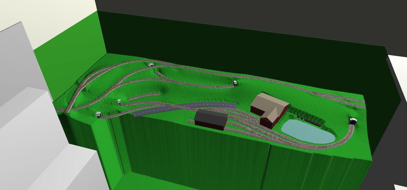
While looking through my copy of 101 More Track Plans for Model Railroaders, for ideas, I came across a layout called Epithet Creek, first published in the October 1972 issue of Model Railroader.
It's 8ft long, by 2½ft wide
Bridges, steep grades, a switchback, sidings for logging camps, and several lines running off the board - which could function as mainline interchanges or future expansions, space permitting.
Extending this to 11ft long on the right-hand end, I could get a longer mainline, and longer tail on the switchback. Additionally, a 2-track loco shed, loco servicing, storage sidings and a log unloading line could be made to fit in the bottom right corner of the layout.

13/01/2019
After a few days of work in the garage, the modular table frame is finished. The modules were roughly sized to make them easier to move around, and not interfere with any future pointwork.
At this point I've lost count of how many times this pine's been reused in various table frames (4th or 5th?), and am determined that this will be the last table frame for a very long time. Some timber was spare in the past, and was used to mount various objects for spray painting, which is why some bits of timber have paint on them.
Incidentally, three of the legs were originally part of the stiffening frame under the last HO layout.
Once all the sections were completed, they were tipped upside-down on the floor, clamped together accurately, and holes drilled through the frame ends for the bolts, that will join and align these separate tables.
The holes were drilled to 5.5mm diameter. With the tables still clamped together, M6 bolts were then driven through the holes with a battery impact drill. This forced the bolts to form a tight thread in the holes. Nuts and washers are also used to keep it all from coming apart.
I know, this is very poor practice, but for something that's only intended to be taken apart and moved twice at most, I think I'll get away with it.

After drilling and "tapping" the bolt holes, the tables were separated and set up one at a time, on some large offcuts of 2" house insulation foam. There's a lot of overpriced shoebox-sardine-tin units (like what I live in) being built around my area, and it's amazing how much good material winds up in the builders' skips.
All those letters and numbers in permanent marker are from various table incarnations, to help me keep track of which bits of timber go where. At this point, most of them are irrelevant - the trick of course, is knowing which ones not to ignore.

This foam of course needs to be cut down to fit the modules. I will not cut foam without a heated cutter. In this case, literally a hot knife, as I don't see the need to spend upwards of $60 on a special hot wire cutter. I don't fancy messing about with resistance wire and current draws, either.
Here, I have a cheap $3 knife, with a piece of old T-shirt rag wrapped around the plastic handle, and held in place with zip ties. The rag is then soaked through with water - this stops the handle being melted when the blade is heated. A small butane torch heats the blade to a dull red heat.

The knife then scythes through the foam - until it cools, which is much faster than usual because the tip is in this case, in constant contact with the concrete floor.

After many reheats, the foam is cut around the module frame. The foam is marked for each module with a letter, to make it easier to put the right pieces of foam with their corresponding modules.

The base layer of foam is finished, and makes for a surprisingly solid and light table. Saving weight is important, because the room in which these modules are to be installed, is upstairs.
This is quite frankly, a huge pain in the arse. The legs were given new numbers to correspond with the table/module frames, and unscrewed from the frames. The doorways in this shoebox unit are just too narrow to get the tables through them and upstairs, with the legs fitted.
This is quite frankly, a huge pain in the arse. The legs were given new numbers to correspond with the table/module frames, and unscrewed from the frames. The doorways in this shoebox unit are just too narrow to get the tables through them and upstairs, with the legs fitted.

A few hours later, and the modules are finally reassembled upstairs.
You may be wondering how I intend to get the modules out of here intact, with all the track and scenery on them, when it comes time to move out. Well, none of us are happy living here, and will be looking to move out sometime, from May onwards.
Conveniently, my bedroom has a wide sliding door, to the adjoining balcony off the side of the house.
When the time comes to move out, I'll build a small hand-operated crane on the balcony, and lift the modules down into the back yard. Not as simple as it sounds, of course, but I've managed harder things.

PVA glue applied to the frames, being careful to keep it away from the bolted joints.

I had to work in small sections at a time, due to a limited supply of clamps and heavy objects to hold the foam down.

25/01/19
The joints between modules were then covered over with masking tape, to keep any glue and scenery out.

Most of the points, and some sectional track, was saved from demolishing the last layout. These needed refurbishing for reuse. All remaining rail joiners were removed and discarded. A wire wheel in the dremel was used to clean the rail ends, ready for new joiners when the time soon comes.

After cleaning, all the points were tested for electrical continuity. Some point blades however, were dead. So I took some very fine wire and hardwired all the points, even the ones that were properly conductive, as insurance.
The excess solder was then cleaned up with the dremel. It looks bad now, but the eventual coat of paint will make all the difference..

To save weight, and having to run up and down the stairs between garage and bedroom to cut MDF with a jigsaw, I'm using 3mm PVC foamboard for roadbed.
At $21AUD a sheet, it's not cheap. But it's light; And I can cut it right here upstairs, cleanly and silently, with a very sharp pair of scissors.
At $21AUD a sheet, it's not cheap. But it's light; And I can cut it right here upstairs, cleanly and silently, with a very sharp pair of scissors.

After buying some more points, and with a track plan to loosely base my layout on, I got into working out where to put things the old-fashioned way - by trial-and-error on the table itself, holding the track in place with dressmaker's pins.
The large reminder scribbled on the foamboard, is so I don't forget to vary the length of the sleepers. Looking at old photos of prototype track, you'll notice the length of sleepers will very slightly.
More-so on sidings, branches and industrial lines, of course.
The foamboard fits perfectly on this module without cutting. A weird coincidence. It'll still be cut down as needed, though.

The foamboard will be jointed at the module joints. This way, there will be only a layer or two of masking tape, to cut through when the time comes to move the modules.

27/01/19
Most of the track I'm using is secondhand Atlas and Peco code 100 flex track, bought very cheaply at a swap meet almost a year ago. All of it is "ex-layout". That is to say, it's dirty, has paint on it here and there, the rail ends need trimming and cleaning up, etc etc.
It's less work than it sounds like, especially for the price I paid..
It's less work than it sounds like, especially for the price I paid..

The rail ends were trimmed and cleaned up with a cutting wheel in the dremel, followed by a sanding disk fitted to same.
The first two or three sleepers were then superglued to the rail, to keep the rail lengths consistent at one end. This makes it easier to bend the track to shape in-situ, and mark it for cutting to length.

After marking out, the track is then brought back to the bench and cut to length with the dremel.
As this is a siding, I've cut out some sleepers (and all the moulded-in spacers) to widen the spacing between them. I've overdone it a bit, here, but that'll be hidden after ballasting.

The sleeper lengths are varied with a knife. It's much more varied here than a mainline of the era, but as I'm modelling a logging line with very low track standards, this should do just fine.

Makes quite a difference. When the track is installed, I'll make it look not-quite this rough..

The further up that siding you get, the worse the track gets!
I was going to use some N scale cork roadbed I found dirt-cheap at a toy shop, but realised logging railways don't really bother building track on top of several feet of ballast.

Before I get too carried away laying track, I'd better cut the foamboard to size and glue it down overnight.

28/10/19
After all the hassle of ripping up the pointwork when demolishing the last layout, I've decided to glue the track down, rather than nailing it. Dressmaking pins will still be used to temporarily hold the track in place, though, and the track will be nailed through the sleepers where it runs over module joints, for durability and long-term alignment.
Here, the yard ladder has been glued down with PVA. It's not very strong, and can be easily pulled up, but it's quite adequate for everyday use. When the track is pulled up one day (I hope many, many years from now) it'll be pretty painless.

The track is laid out and adjusted until it looks right, then temporarily pinned in place.

To make sure the gradients weren't going to be too steep, I took some measurements of the pinned-down track, and drew up the layout based on that in SCARM. I then started working out the gradients, making sure the grades and changes between them are smooth, before proceeding.

I've no shortage of timber offcuts, so I'll cut them up further and prop up the track with them, as I did on the last layout. Quick, cheap and easy.

After hacking up a pile of scrap with various saws, I was able to proceed. Here, the next module joint is being thought out.

The small "scrap" supports were then spaced out and glued down with PVA. The track was marked out on the foam, as I'll be pulling it up to fit the foamboard roadbed soon.

The first half of the joint here was glued down and covered with masking tape..

..The second half was then glued into place, and another piece of tape applied over the top to seal it.

After this, the foamboard roadbed was cut out and glued down. Cans of spray paint/glue/whatever make for excellent weights. Track will follow, shortly.

29/01/18
This time around, I want to make the control panel less like last time's eyesore, and instead have it contribute to the overall presentation.
Things like this, this, and this, are the sort of thing I'd like to emulate here, within reason.
If I'm modelling the 30's & 40's, I might as well try and make the control panel to go with it.
Thanks to the hoardes of vapid hipster sheeple jumping on the "vintage" and "steampunk" bandwagons, nice old things of all kinds, are more difficult and expensive to obtain than ever.
But I don't want to just senselessly mash together a pile of random antique components for the sake of looks, like the clowns mentioned above. I have to be careful not to overdo it; Every visible component must have an actual function, rather than just being there, out of place, to look pretty.
Eventually, I found two unopened packs of five knife switches on Evilbay. Not cheap, but being double-pole switches, and there being ten of 'em, they'll be good for block power switches.
While these are vintage, and nothing like what's made today, it's obvious that these switches are still relatively modern plastic things. (1970s?)
They'll need some backdating work in any case. Paint, new handles and straightening the bent terminals, to start with..

I also found this older, slightly larger ceramic-base switch. Thank fuck I had some money saved up. In the end, I'd spent about $200 on just eleven switches..
This switch is much closer to the vintage I'm after, but it still needs a bit of a cosmetic work..
It will be the master on/off switch for the track power.
I also have eight very old toggle switches bought cheaply at a swap meet, which will be used for the future lighting system..

30/01/19
The roadbed here is now complete and ready for track. The latter was temporarily arranged in-situ with dressmaking pins, and the outline of the track transferred to the roadbed. The flex track can then be taken to the workbench to be trimmed to length and have the sleepers cut down. The outlines then help me to place the track in it's correct positions.

07/02/19
The track running from the yard throat at the right, and up to the mainline passing loop is now glued down. The terrain is being built up with smaller insulation offcuts, and the switchback is being started.

08/02/19
The track leading up to the bottom points of the switchback, crosses the module joint.
I'm taking a belt-and-braces approach to keeping the track aligned. The holes for the nails were pre-drilled a little undersize.
I'll cut all the rails running over module joints, when I get a new razor saw..
The blue card is from the Peco point packaging, and makes excellent packing material for track heights.

Yeah, it's ugly, but it's a more durable joint, and will be made much less noticeable in time.

Switchback grade glue drying. Dressmaking pins are useful for holding the curves in place while the glue dries. I then pull them out with pliers.
The ruling grade here is 6%. In hindsight, I really should have tested this with a train or two before gluing it all down..
A stream will go through that gap in the roadbed..

For the curve leading into Logging Camp 2, I used a piece of 18" radius sectional track as a template for curving the flex track. The sleepers were then given some spots of superglue to hold the curve.

Camp 2 in the back, and Camp 3 in front. The latter's track yet needs trimming and gluing down. Both camps' tracks were made level, so wagons won't run away when shunting.
Camp 2's siding goes off the sub-roadbed and floats for about 8", because the siding will run onto a short stub of trestle - a detail of the original Epithet Creek plan that I liked enough to include.

11/02/19
The hot knife and a pencil torch were used carefully to carve out the rough shape of the stream. Open doors and the powerful ventilation fan in the en-suite were used to get the toxic fumes out quickly.

Working out the control panel layout. A pair of analogue meters, for voltage and amperage were bought on Evilbay for $15 each. There's just enough space on this module for the complete set of controls, including a diagram showing which sections of track are switched on, and a bracket to hold the walk-around throttle.

12/02/19
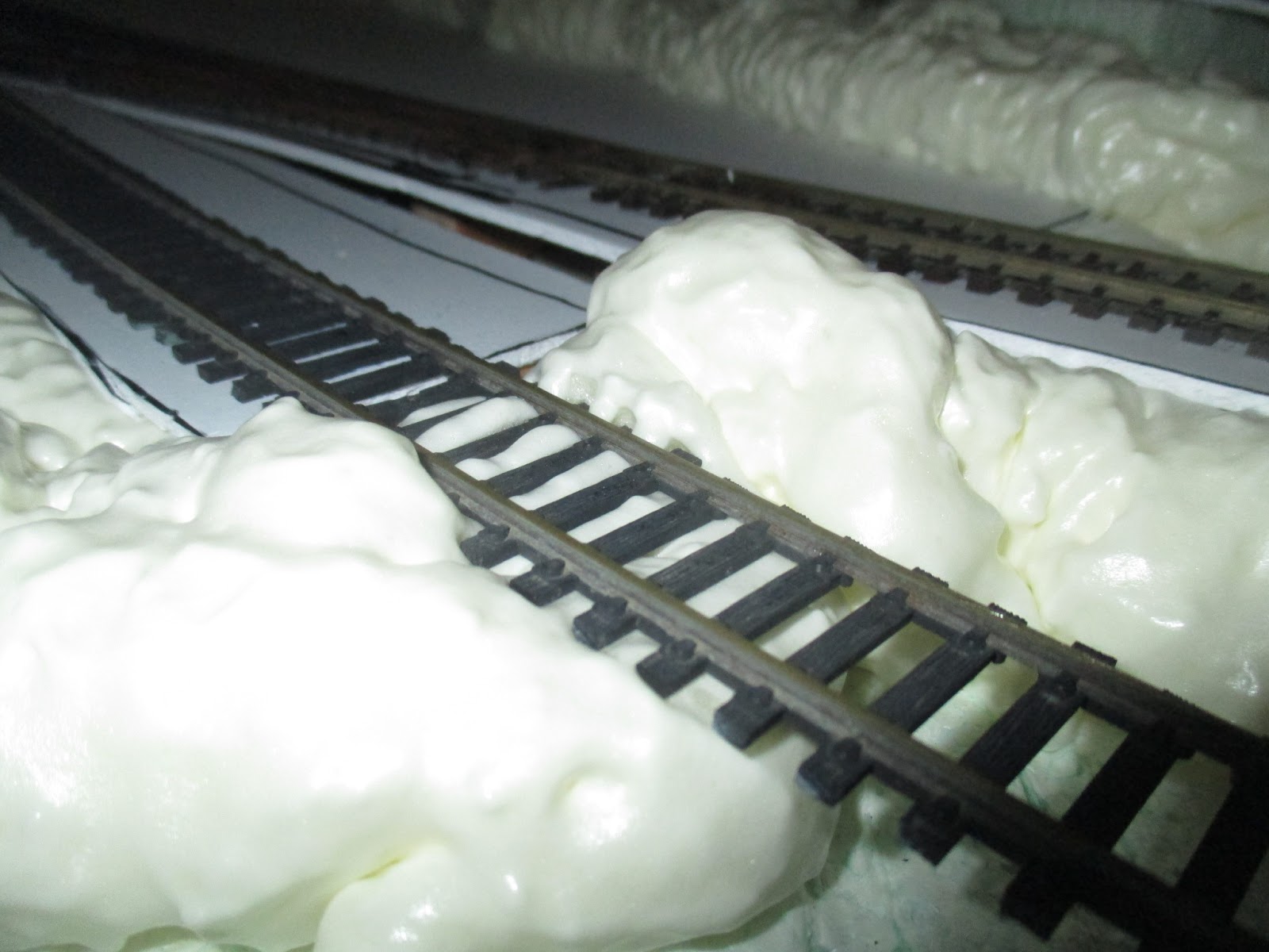
There was some unwanted expanding foam leftover from a repair in the kitchen. No-one else wanted it, so I figured it'd be interesting to carve the terrain from solid foam, rather than building it up with the usual papier-mâché.
It's very satisfying to use, but depending on the brand and quality, it will expand a lot more than you'll expect. It needs to be used very sparingly.
This stuff is polyurethane-based, so the only solvent that will touch it is acetone, and that's only before it cures. I don't have any acetone. The only way it can be removed once cured, is mechanically. So be quick about cleaning up before it cures, and wear disposable gloves..

In some cases, it threatened to engulf the track. While it was still wet, I tried using the straw to pick up and discard some of the foam before it got to the track. Weirdly, the wet foam can't be picked up - it's more like popping bubbly detergent froth in the kitchen sink.

This section is tricky to reach at the moment, so the track was hurriedly covered with masking tape, in case the foam expanded any further. Thankfully here, it didn't
I've decided this section of track will be a mainline interchange. I'm thinking I'll disguise the end of this track with a tunnel mouth at the layout's edge. I think a tunnel can be acceptable on a logging line, if it's for an interchange.

Apologies for the brightness of the flash; This foam is difficult to photograph.
After a couple hours, the foam was cured enough to trim a little of the excess away.
The tracks "hanging" over the future stream got a little foam on them, and will also need to be scraped clean.
 The offcuts were put to use filling gaps.

The results of one can.

13/02/19
The outlines of the meters were drawn onto the side of the Eastern end module and cut out with the hot knife.

With the foam out of the way, the meters could then be pushed in to more accurately mark the timber for cutting out.

The tracks "hanging" over the future stream got a little foam on them, and will also need to be scraped clean.


The results of one can.

13/02/19
The outlines of the meters were drawn onto the side of the Eastern end module and cut out with the hot knife.

With the foam out of the way, the meters could then be pushed in to more accurately mark the timber for cutting out.

The laundry bucket was pressed into service as a debris catcher, and the timber chain drilled.

A coping saw was then used to open it out and smooth the edges a bit.

A screw holding the frame together was cut off in place, with the dremel.


Test fit looks promising. The gauges themselves are just cheap ones from China on Evilbay. They're a little modern, but just close enough for me. The cases will need painting to get rid of that horrible plastic sheen, though.

I've weakened the frame considerably by doing this..

So a spare piece of pine was glued, clamped and screwed (almost excessively) to the frame to strengthen it. Hopefully this will be enough to stop the module flexing and distorting when we move out.

The master shutoff switch needs a fair bit of work. This corner is missing from the ceramic base, and I might build it back up with bog, before painting the base black. I'm not familiar with painting ceramic, so will have to look into that..
The wooden handle has had a crude repair in the past, and is being made presentable again. The screws are all rusty and horrible - replacements are on order as nothing suitable could be found locally.
Spot the difference, left is as standard. Yes, I am truly that pedantic.
I should probably try removing all the weird numbers and symbols from the faces. Older dial faces aren't usually this cluttered.

18/02/19
The switchback tail/headshunt is installed, and another can of expanding foam has been applied. This time, any track in areas to be foamed, has been protected with masking tape.

23/02/18
Something I should have remembered to do as I was laying track, was to solder the power feed wires to the underside of the joiners before gluing the track down. It's a bit harder to do it in-situ, but not impossible.
Here, I'm drilling a 5.5mm diameter hole through the roadbed and 2" foam base.

I happened to have a packet of plastic drinking straws leftover from another project.
So one is cut to length and glued into the hole with PVA.

The smooth plastic straw makes it far quicker and easier to pass the wires through.

The wires are then soldered to the bottom corners of the joiner sides. After ballasting, they won't be visible. A piece of modelling clay or masking tape will be used to cover the hole, stopping the ballast from falling through.

24/02/19
The wire connections between the modules will be done with terminal block connectors, hot glued to the 2" foam. I didn't line these two up very well, will have to realign one of 'em.

The 5.5mm drill bit is too short to get through the thicker layers of foam. Yes, I should've drilled the wiring holes earlier, glued in the straws before applying the expanding foam, and soldered up all the power connections when I was laying the track here.
But heating a piece of aluminium tube with a torch works well enough..

..To cut straight through all the foam.

25/02/19
After weighing up the risk of irreparably damaging the white finish on the dial faces, I tried removing those superfluous alien hieroglyphs with a cotton bud dipped in Brasso. It's worked very nicely, with no discernible damage to the white surface.

As mentioned further up, I realised I'd forgotten to make sure my weakest and "slipperiest" loco, could handle a load up the switchback's 6% ruling grade.
So before building any further, I made up a quick and very dirty power connection for my walk-around controller, then gave the track a damn good going over with the cleaning block and vacuum cleaner.

The aforementioned weakest, "slipperiest" loco, was my first steamer. A Richmond 4-4-0, of Bachmann's Spectrum line.
While they're a fine loco, they are known to be a little under-powered and prone to slipping on grades.Four wagons (the passing loops' capacity - Christ, that's depressing) were coupled on to make a supply train. There was some slight slippage at the steepest part of the switchback, but nothing serious.
I think some Bullforg Snot on one driving wheel (or better yet, finding a place to squeeze in some more lead) should sort that out.
Locos like this were designed for moderate to high speeds, on the well-built track of mainline railway companies. But by the 1910s-20's, these fast 4-4-0s were rapidly being superseded by larger and more powerful designs. The mainlines, looking to dispose of them quickly, put these locos (many being near brand-new) up for sale at bargain prices.
Logging railways have always been notoriously stingy, so locos like this became a common sight on logging rosters. They weren't at all suitable for the rough track and low speed grunt work, but they were cheap and readily available, so the loggers made do with them - usually on track maintenance and supply runs.
Besides, this is a really nice model and it'd be a waste to get rid of it.
The fancy livery is a bit odd for logging, so, erm, let's just say this is the manager's favourite loco, and as such, is to be the best-kept. Yeah, that sounds convincing enough!

I don't like having to tug on the wires to pull out the connector plugs between that loco and it's tender, to put it back in it's box. I also don't like handling HO locos and rollingstock in general, for fear of damaging them. So I've pulled my finger out, and finished laying the sawmill yard tracks. For the foreseeable future, the loco will live on the layout, ready for test runs.
The "Walthers 2-Track Engine House" kit has been temporarily erected with masking tape, to keep the dust off the loco.

I'm not yet sure if I'll use the brick-patterned walls, or make replacement walls from styrene to look like a timber shed. Timber's cheaper than brick, so it makes more sense for a logging loco shed.
In any case, the building will be getting a full interior and lighting in due course..

28/02/19
I decided to wire up the West end module first, as it's the smallest and simplest to wire, so as to ease myself into the wiring process. I'm an electrical moron, and this level of complexity is the highest I'm capable of; Quite honestly, that suits me just fine.I won't go into much detail on general track wiring, as many, many, many others in literature and on the internets have already described it, far better than I could.
The black (negative) common wire was run out first, followed by the red positive wires, that will lead to the track power switches. In an attempt to keep the runs tidy, I've elected to twist all but the common bus wire together, and keep them from hanging down, with picture hooks pushed into the foam. Intersections and joints are by way of chocolate block connectors, for ease of disassembly if/when needed.

02/03/19
Middle module is wired up after two sessions of work. The removable "jumper" arrangement at the module joints isn't as pretty as I'd like, but I realistically think this should all work reliably, and be simple enough for me rectify any issues, should they pop up in the future.Besides the jumpers, I'm pleased with the tidy "subway map" appearance of the wiring runs.

While I did have holes randomly drilled in the module frames to pass the wires through, I found they were poorly-placed, if I wanted to keep the wiring runs tidy. So I carefully used the small butane torch to melt a small gap in the foam, over the frame bearer I wanted the wires to pass over.

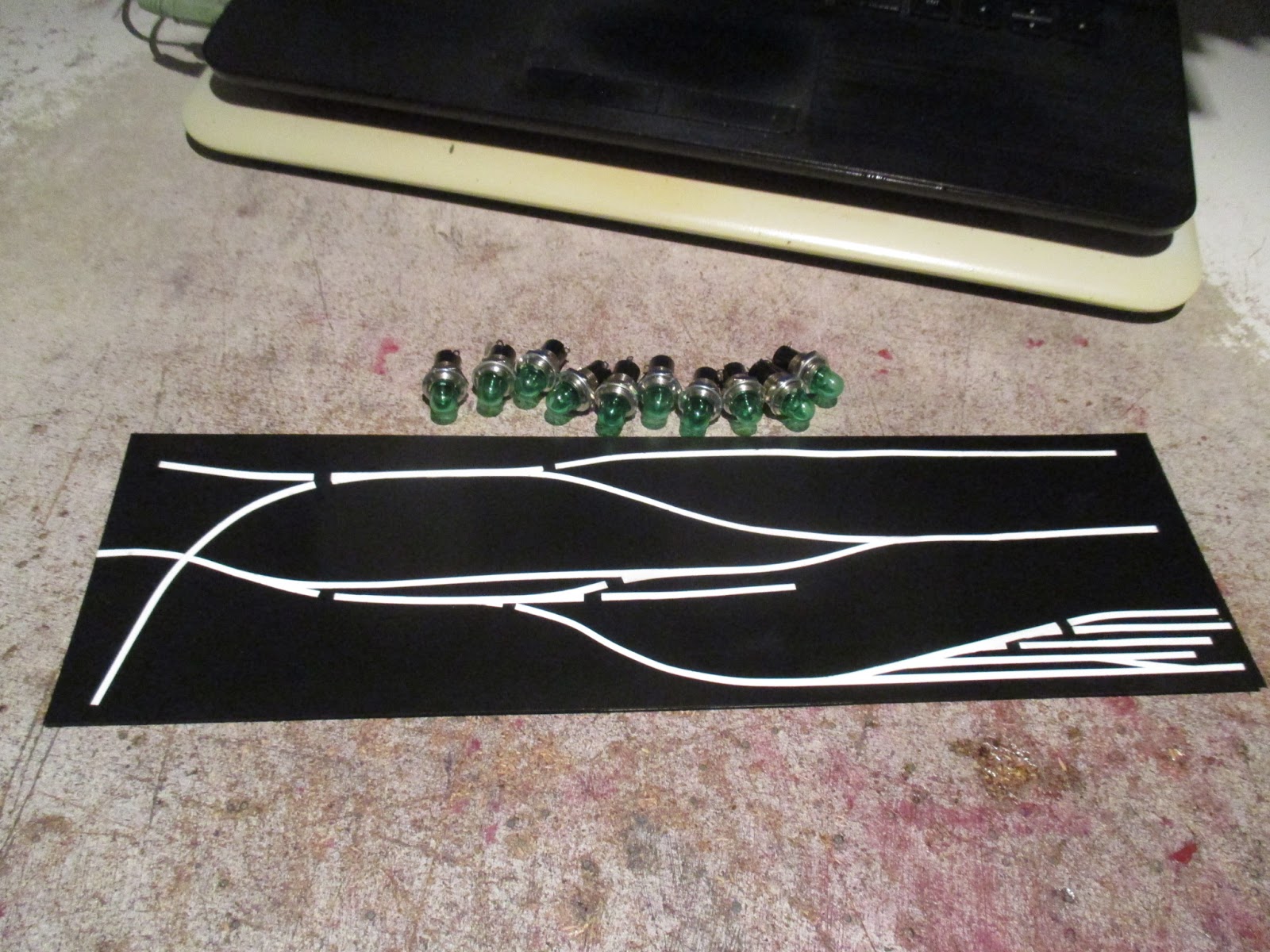
I'll need something like a signal box mimic panel, but for track power indication, rather than point/signal control.
I took a screenshot of the layout in SCARM, and edited the resulting image in Microsoft Paint.
The diagram is sized to fit across an A4 sheet of paper. The print-out will be used to make the actual diagram that will be fitted to the layout.

06/03/19
Yesterday, the track was masked off, and another can of foam applied where needed.

Although I quite enjoy carving terrain from expanding foam, it's cost me $65 to do so. Papier-mâché would've cost about $2, and albeit, a lot of time scavenging for Propaganda-Print.
Thankfully I needn't buy any more foam, the terrain is fully built-up.

I had almost half a can leftover, and as these cans tend to render themselves unusable if left part-used, I figured I'd use it up by filling in the cutting where the mainline interchange runs off the layout's edge. I'll cut a tunnel into this once it sets.

The knife blade was bent at the handle, to allow a better shape to be carved here.

Another thing I don't like about expanding foam, is just how much of it inevitably ends up in the bin.

The tunnel area was given an extra day to cure, due to it's thickness.
I'm not yet fully happy with it, but I do think actually digging out this tunnel, has given a better result than I've previously managed, building them from papier-mâché.

The bore is a bit oversized right now, but it'll have a realistic rock-textured liner in there, eventually.

14/03/19
The horrible plastic cases of the volt and amp meters, were sprayed satin black. Unfortunately, the lenses couldn't be removed without destroying them, so they were replaced with new plastic.
The layout will have it's own day and night lighting, so the room's lights will be turned off when the layout is in use. So in a darkened room, with only the layout lit up, the amp/volt meter faces will need illumination.
A pair of 2.5mm holes were drilled in the bottom of each case. Here, I'm testing the bulbs' fit. They're 12V grain-of-wheat. Not yet sure just which lighting circuit they'll be wired into..

Some white paint to help direct the light properly. No idea if it'll make any difference, but it can't hurt.

Wires soldered and isolated.


The modern meters will never be quite the same as period-correct ones, but I think they'll do well enough.

23/03/19
A piece of 0.5mm styrene was cut, and taped to the layout diagram printout. It was then illuminated from behind, and 3mm wide tape (for decorating fingernails apparently) was carefully applied along the backlit lines. This tape will function as masking tape. Excuse the hastily-written reminder, my memory's not getting any better.

A crude but effective means of backlighting.

I'll spray this lightly with clear paint, to stop the later coat of black paint from bleeding under the tape.

A few coats of satin black later, and it looks pretty decent. The panel lamps are just standard ones from Jaycar.
Unfortunately, the width of the fingernail tape varies by about 0.25mm, so the lines are slightly wavy. Realistically, I don't think it'll be noticeable when in use.
The holes in the tops of the track power switch throws were filled in with bog, and the little plastic "handles" cut off.

Ever since I bought these switches, I'd been grappling with how to make replacement handles for them. I tried turning some from oak dowel, but that was unsurprisingly, a shitshow.
It then dawned on me that I'd recently bought a stack of 1:24 scale windows and doors from a doll's house supplier, for my garden railway buildings. "What about staircase posts?"
Turns out they're called "Newell posts", and there's plenty of shapes and sizes available, machined from wood. A couple weeks later, I had a dozen to hack up into knife switch handles.

One careful, straight hacksaw cut..

..Then it's into the drill press for some "turning". With the drill at it's highest speed, and some coarse emery tape, the cut end is reshaped.

I did the first handle by eye, then carved a popsicle stick with the dremel, to make a shape template, to fit the first handle. I could then use this as a guide, to make the other nine handles to match the original.

Another careful cut, and clean up by hand.

I think this'll work. Just need to drill out the bottom of each handle and glue in a 3 or 4mm pin or bolt as a strengthener.

27/04/19
The anachronistically-modern Gaugemaster "Combi" walk-around throttle (to right) was never going to look right with the rest of the control panel. Operationally however, it's an excellent low-speed controller.
Older, more aesthetically-suitable controllers simply can't give running anywhere near as smooth as their modern counterparts. Not to mention nearly all of them are heavy, bulky things designed to stay put in one place, rather than carried around a layout.
By chance, I recently happened across this old walk-around controller, (to left) at the Caloundra Model Railway Club's table sale, for $15. Perfect - I can clean up the old case and knob, then swap out the original innards with those from the Combi.

30/05/19
Test running of the layout continues, with the temporary power connection. The foam has been cut with the hot knife, along all the module joints. Once the track wiring is done, I'll cut the rails at the joints.

At this point, I heard my circumstances were to change, affecting me around the end of the year. Suffice to say, the layout may have to be stored for up to three years, until it can be permanently installed in a dedicated layout room - that is to say, most likely a refitted caravan.
Well, that's the current plan, anyway.There isn't much more I can, or should, do to the layout, until it's permanently installed. So it's mothballs for this, and back onto other projects for me, until then.