Of
the few end-platform coaches available in the garden gauges, none
really took my fancy, and for once, I really can't be bothered building
one from scratch. I eventually realised
IP Engineering's Gladstone Coach kit would make suitable fodder for bashing.
------------------------------------------------------------------------------------------------------------------------------
21/01/19
The
kit has arrived. Unfortunately, the bogey frames, bearings and
couplings were missing - as sometimes happens with orders from IP. If
you can get onto him, Ivan is generally very helpful regarding
replacement parts. I didn't bother, as I planned on fitting different bogeys, and have a pair of spare couplings.
I've
temporarily assembled the coach with Blu-Tac to get a better
understanding of how it goes together, and to have a long think about how
best to proceed with the bash. I expect a lot of mock-ups ahead, as I'm making this up as I go.
I must say, I can't understand why
so many people don't like MDF for rollingstock kits. With spray putty or
filler primer, or sanding sealer, or wood
hardener (all being very readily available), it's
far quicker and easier to work than plywood.
Personally,
I don't much like plywood. The grain is naturally over-scale, and
understandably from a production standpoint, often facing the wrong
direction, as here. It's more difficult and time-consuming to hide the
grain on ply whilst preserving the laser-cut scribing, than it is sealing MDF to make it workable.
Additionally, plywood is less stable than MDF, prone to warping with changes in humidity.
Looking lengthways down the floor, I wondered if I could straighten it..
As
originally thought, I've decided to cut the semi-open ends away from
the glazed centre saloon, using the accurately-scribed panel lines as a
guide. The wood is repeatedly scribed until the parts separate. Any
minor clean up is done with an emery board.
Whilst
this would certainly end up a very attractive little coach, at just 10"
I do feel it's a bit short. I'd like a longer coach for some contrast to my other stock, but that'd require another Gladstone kit to cut up for a longer saloon. I don't want to spend another $200AUD, so a short coach will do.
22/01/19
Scribing the saloon
ends to match the sides.
Note the
"chipped" areas at the bottom. The ply split along the grain in these
areas, when I scribed the lines in a downward motion. Scribing upwards
helped avoid this, but it's yet another reason I don't like plywood
kits.
Because of the relatively-large side windows on this coach, I'll regret it later if I don't scribe some interior window and door frame detailing.
Left panel is as standard, right is modified. A small difference, but will show up better once painted.
The rear faces of the end walls were scribed to match their front sides.
The kit's solebars were cut down to length, and the fragile wooden truss rods discarded.
While
Blu-Tac again handles most of the work in this mock-up, I'm holding the warped floor
down so that it's straight. I'll have a go at straightening it with hot water..
The floor of the end platforms looks far too thick,
at 3mm. I'll cut it down to match the saloon length and cut new
platform floors from styrene or coffee stirrers..
23/01/19
To fill the grain, I'm using cheap spray putty from Supercheap Auto.
The
first light coat has already made the grain much less noticeable. As
expected though, it's started to fill in some of the scribed lines. I'll
re-scribe them with a knife, give it all a light sanding, brush away
the dust, and re-coat.
A
sharp blade used slowly and carefully, will minimise the chance of
slippage and cutting new, errant lines. The light sanding will really
help smooth the roughness of the material, and help hide any accidental
knife-slips.

03/04/19
I still want to build
longer rollingstock, which would look far less "toy-like", but I said earlier, it'd just
be too much extra work and expense to lengthen this coach.
I'm
now thinking the explanation would be, that the local shire was in need
of another coach, in addition to it's existing locally-built pair. A new coach couldn't be built soon enough locally - for some plausible-sounding reason, so
the shire bought this tiny thing very cheaply, secondhand from some tramline that closed. It's a bit small for what's needed, but they make do
with it.
That's good a enough excuse for me.
The cast
whitemetal door handles in the kit are nicely made, though the longer
handles are very delicate - two of the four were already broken.
I'll use the two smaller handles for the saloon doors. New rails of a
more suitable shape and length, for the end platforms, will be bent from
the 1mm spring wire on the right.
After failing to straighten the floor with hot water, it was
binned. A new floor was cut from 3mm PVC foamboard; as it was on hand,
easy to work, same thickness as the plywood floor, and never warps.
A steel ruler was aligned with pencil marks at either end, spaced at 5mm.Two light passes with the knife left a sharply-defined floorboard effect.

04/04/19
I'll be using a pair of IP Engineering's
small whitemetal bogeys.
I've two pairs of these things to build, so the castings will all be fettled at once to
save some time.
Needle
files and the hobby knife were used to clean up the castings. Half the
time spent on this, was just unclogging the files with a blunt knife
blade. I found that lubricating the files with graphite, by rubbing a
pencil on them, slightly helped to slow the files' clogging up. Even so,
I found it was best to minimise having to use the files at all, doing
whatever I could with a sharp knife.
A few hours later, all the castings will be ready for assembly after degreasing with a toothbrush and meths.
I prefer to use nylon/fibreglass wheels from
Binnie Engineering,
simply because of the various patterns available. Binnie wheels have 3mm
axles, whilst IP wheels use ⅛" (3.18mm), so whilst the Binnie axles are a
rattle fit in the IP bearings, it's no issue. There's a small "pip"
leftover on each flange, from moulding the wheels. These are quickly removed with an emery board. But when I have a lot of wheels to "de-pip", I
do it on the lathe with files.
The holes cast into the backside of the bogey frames are
very
nicely cast. No flash to remove, and the bearings are a tight
press-fit. I like to use my little smooth-jawed vice for this. A tiny
drop of ordinary thin superglue, spread around the joint between
bearing and axlebox, is added insurance.
A
dry assembly found the ends of the bolsters needed filing down
slightly, as some ends were a little too wide to fit into their
corresponding sockets in the backsides of the sideframes.
That
done, a bead of thick, shockproof superglue was applied around the end
of the bolster. I'd normally prefer JB Weld or another epoxy, but
couldn't have been bothered mixing it. Ordinary runny superglue may be fast-setting, but it's resistance to everyday shock (rough
shunting, minor derailments etc) is almost non-existent, rendering it
nearly useless for running gear work, in my experience. I'm uncertain of
the shockproof glue's long-term suitability for bogeys, but
realistically, I'd only expect it to let go if the wagon had a
major derailment.
After
joining bolster and sideframe together, the joint is "tacked" here and
there with the standard superglue, so I don't have to hold the parts
together while the shockproof stuff sets.
Before the "tacks" fully set, I check again to ensure the bolster is as square as possible with the sideframe.
Another
bead of shockproof superglue applied to the other end of the bolster,
and the other side frame was fitted. This is a bit fiddly, getting both
axles and bolster lined up all at once.
The
bogey is sat on a piece of plastic track to ensure all wheels
are squarely on the rails. Neither of theses bogeys needed adjustment,
and the second bolster joint was tacked with superglue. That completes the bogeys.
Emery boards are
great for sanding the window openings. Most of the sanding is done with a fairly new board,
cutting through the bumps and lumps pretty quickly. An old, worn board
is then used to finish up, and smooth out the scratches left by the
newer board.With that, filling the grain is finally done, and the coach can be assembled.
08/04/19
A
heavy-duty wire brush does an excellent job of distressing the foamboard floor to
provide a wood grain effect. It's also shown me how overdue for
cleaning the brush is, leaving a lot of dirt highlighting the new "wood
grain"..
Some paint and washes, and it should be hard to tell weather this is actually timber or PVC.
Erecting is always tricky and a bit nerve-wracking. A light film of KS
Bond was applied to the bottom 10mm of the side walls, and the outer
faces of the solebars, then the parts pushed together, again tacking
with superglue from the inside, flowing it
into the joint, rather
than on the surface of the joint. With both side walls attached, an end
is clamped roughly into place. No glue was applied before clamping.
Using
a steel ruler, the wall is pushed inwards so it's perfectly flush with the
ends of the side walls. The clamp trigger is given another squeeze to
tighten it all up a little. A second clamp at the bottom is also a good
idea, at this point.
Superglue
is sparingly applied into the joint at the top, being careful not to
over-apply, which would dribble over the outside of the joint. A second
drop or two, is applied to the inside corner just under the windows, and
allowed to run down to the floor. A small scrap of rag is good to soak
up the excess glue on the surfaces, allowing what did soak into the joint,
to do it's job.
PVA for this job would be stronger, but with superglue, I don't have to be paranoid about just
breathing on the joints for the next four hours.
09/04/19
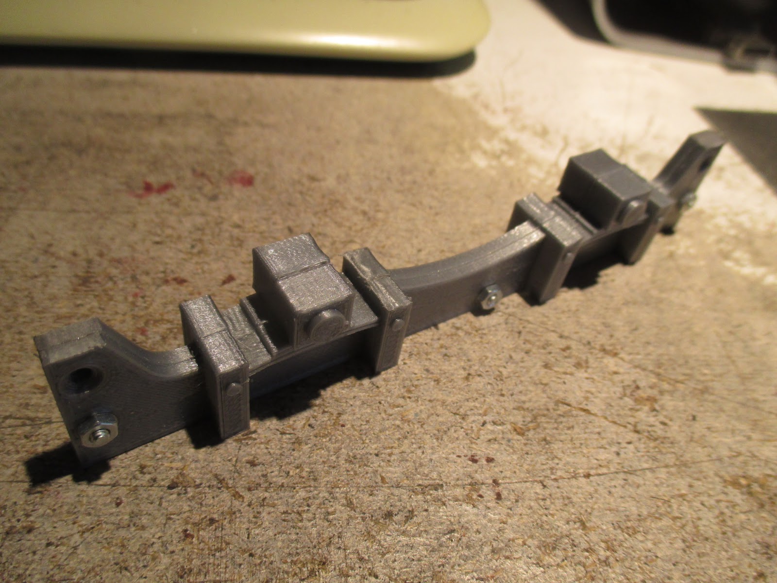
The
bogey kits come with very nicely-cast mounting pivots. Included are
self-tapping screws to attach the bogeys to the pivots. As a rule, I
loathe self-tappers. It's all to easy to strip out a hole with them,
leaving the hole often impossible to repair.
So I
drilled out the pivots to 2.5mm, and threaded the holes with an M3 tap.
M3 screws had their heads cut off, and were loctited into the castings
to make tidy little mounting studs.
A nut and washer retains the
bolster. some low-strength thread-locker will stop the nut from unscrewing in service.
16/04/19
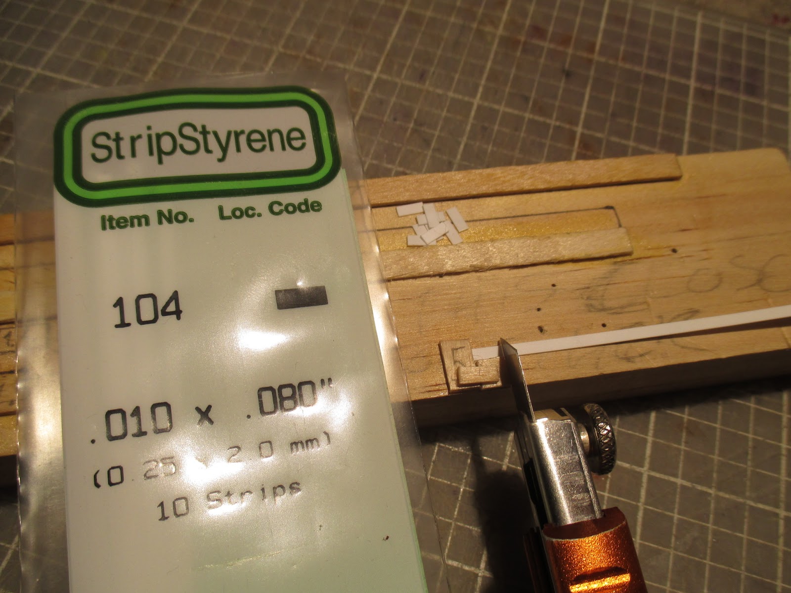
The centre line of the wagon was marked, and the ride height determined by trial-and-error with styrene and foamboard off-cuts.
I've decided to use 2mm styrene for the end platform floor. Strips of 1mm styrene packing were glued on top of the solebars, to bring the 2mm platforms up flush with the bottom of the end doors.

Although I don't plan on using 2ft radius curves ever again, I would very much prefer that all my rollingstock be able to do so, should it be required for hidden storage sidings, etc. The bogeys
slightly foul on the solebars, when testing on a section of Newqida track.
In the areas around the bogeys, 2mm of the solebars' width was removed with a sanding disk in the dremel.
04/05/19
The end platform floors were cut from 2mm styrene, and finished in much the same manner as the foamboard interior floor.
05/05/19
Propping up the wagon, making sure it's perfectly perpendicular to the cutting mat on which it's all sitting.
With that in place, two lengths of styrene angle were glued into place. These will help in accurately aligning the end walls, and strengthen the joints.
A good bit of fiddling later, one end wall is clamped accurately in place.
The gap between the saloon body and the end wall was measured at top and bottom, to ensure the end wall is vertically square with the rest of the coach. The clamps holding the end in place were pulling it on an angle. The wall was carefully pulled back and held in position with one hand, whilst the other hand tacked the wall in place with superglue on the inside of the joint.
After the superglue dried, the clamp was removed and the back of the joint was epoxied. The process was repeated at the other end.
For durability and
ease of construction, I'm going with something like those steps commonly
fitted to tram trailers. This seems fitting, considering the coach is
generally built like a tram trailer.
At this point, I could step back, take a good look at the coach, and think about where to go from here.
A simple jig was made up from two HO track nails and scrap of pine, to bend the hand-rails.
06/05/19
In addition to the hand-rail bending jig, I needed another to accurately drill the mounting holes. This was just a offcut of cheap 4mm ABS angle, very carefully made to match the handrails.
I took my time drilling the mounting holes, as any fuck-ups here would be very hard to fix properly. Despite the crudity of the jig, it all went quite well.
06/05/19
2mm styrene was cut and sanded to an accurate fit into the end platform tops.
16/05/19
A new knife blade helps in cutting the seat slats from their fret. The remaining stubs of fret were removed with the dremel.
06/06/19
After a light base-coat of red oxide primer, I dug out an aerosol can of Tamiya's TS-33
Dull Red.
12/06/19
After it had cured, the coach was hit with a satin clear acrylic aerosol. This was give the appearance of a more recent addition to the wagon roster, as opposed to the flat finish of the older coaches.
04/07/19
The end-platform floors and steps were brush-painted with Tamiya's XF-1
Flat Black, and the interior walls in two coats of XF-78
Wooden Deck Tan.
The saloon floor had two thin, grungy coats of XF-52
Flat Earth, followed by various homebrew washes made from Tamiya acrylics and alcohol.
The window frames were painstakingly picked out with XF-68
Nato Brown.
05/07/19
Due to all the coats of filler-primer and paint, the panel lines on the exterior are getting close to entirely filled in, and as such are useless in helping me keep the window-frame paint where I need it. Some Tamiya 3mm wide masking tape was bought.
I've never used it before, but the cardboard centre of the roll has the word "Nitto" on it. That's a brand of electrical tape. I thought this 3mm stuff had a familiar feel and "stretchiness" to it.
The fact is, though, that Tamiya's repackaged electrical tape is simply too thick for this sort of job. It can't be properly burnished down around the window corners. As a result, the brown paint has run under the tape. I should've cut down some of Tamiya's excellent very thin paper masking tape (that I already had on hand) into strips, for this job.
12/07/19
Predictably, as water wasn't enough to remove the brown paint, and after trying to use alcohol on a cotton swab to remove it, the satin clearcoat turned white.
I ended up spraying some red paint into the can's lid, and brushed it onto the whitened spots. Followed by a light coat of satin clear over the touched-up areas for a (semi-reasonably) consistent sheen. The windowframes and black ends were carefully hand-recoated closely enough, as the clearcoat darkened them unevenly.
I'm not at all happy with the finish of this coach, but to fix it, I'd have to strip everything back to bare again. That alone would involve breaking the coach back down to it's components. Not worth the trouble. All things considered, the overall finish is excellent, just not quite up to my usual standard of fanatical masochism. At this point, even I can't make out the flaws from 2-3ft away
.
Interior vents, recessed panels and doors were painted, then the door handle holes drilled with the pin vice.
The seat frames were glued in with PVA, applied with a flat-blade screwdriver.
A pair of needle-nose pliers were essential in fitting the free-standing seat frames.
14/07/19
Each of the slats needed about 1.5mm trimmed off the end, to fit this modified saloon.
A fine-tipped superglue applicator, and a scrap of rag to wick up any excess glue, were indispensable in fitting the slats.
19/07/19
I'm moving house in a week, and as the coach will need safe storage/transport in any case, a suitable box was made up. As I do for most of my rollingstock, I "cut-and-shut" an existing cardboard box or two, and glued in some scrap eggshell foam as padding.
These homemade boxes look like shit, but they do the job. I'd like at some point though, to come up with something more presentable..
After some swapping around with other stock, a pair of small IP Eng. couplings were freed-up. They're still weathered for the wagon from which they came, and will be partially-repainted to suit this coach.
30/07/19
Having re-established the works after the move, I can get back to work. A 1.8mm hole was drilled in the floor at one end of the saloon. Some 2mm OD copper tube was cut to length. The wires for the interior light will run up through the floor and tube, to the ceiling.
The two door handles included in the kit are identical to those used on my existing pair of coaches and
guard's van. Using two spares from those kits, I can fit handles on both sides of the doors of this coach.
I wasn't looking forward to making the hand-rails' mounting flanges. A 5mm jig was added to my block of strip-length-cutting jigs, and sixteen tiny styrene tabs cut from the strip.
Each tab needed an 0.9mm hole drilled in it's center. These were done by eye, and they came out surprisingly well. I try to get as much use as possible, from my eyes and steady hands, whilst I can.
After I cut off the heads of sewing pins to use as rivet detail in projects, I usually keep the headless shafts for odd jobs like this. The shafts are pushed (with pliers) into a block of wood, and used to hold the tabs whilst they're painted flat black.
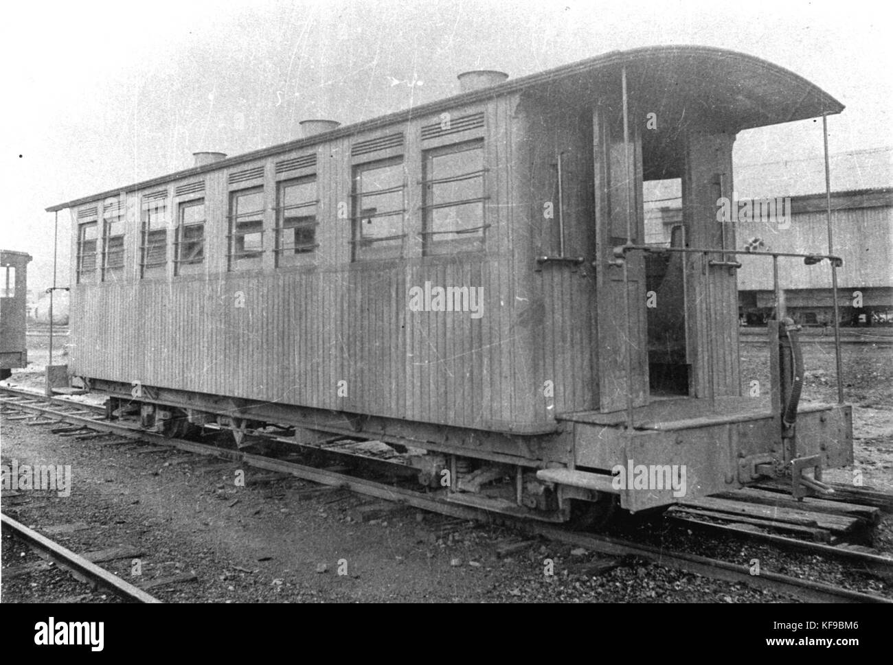
The tiny tabs make reasonable mounting flanges. These were loosely based on those fitted to
North-East Dundas Tramway coach "A-1", now running on the Redwater Creek Tramway in Tasmania.
25/08/19
Time to stop putting off fitting the window panes. I'll be cutting down the clear plastic material provided in the kit.
I bought some canopy glue a few months back, for better results in window-fitting.
A drop was applied to some scrap packaging, and carefully-applied with a flat-blade screwdriver - I don't want any glue getting squeezed out from behind the uprights when the pane is fitted.
After fitting the panes, some more glue was applied along the top for extra strength.
25/09/19
Before I can fit the end panes, lighting and roof, I needed some passengers. All the figures I had were 1:24 scale - much too small for even this tiny coach.
Eventually, I said "fuck it" and spent $50 on a pair of Bachmann's
Scenecraft 16mm scale figures. Expensive, but well worth it, where they'll really be seen in a coach like this.
The 1mm thick styrene roof from the kit was cut to length, holes drilled for the roof vents, and the underside scribed and distressed to look like timber. As I want a white ceiling, the styrene wasn't painted.
The arches were painted white, one of them had a notch filed out for the wires. The copper tube was painted to match the interior walls.
A small bulb-holder (I believe salvaged from a car's instrument panel many years ago) was painted and fitted with a 3V grain-of-wheat bulb. As you may have read elsewhere on this blog, I loathe LEDs. Nothing looks more like an incandescent bulb, than an incandescent bulb. Some very fine wire was carefully arranged and superglued into place.
Some time and care with a ruler and superglue yields a nice tidy run of the wire. I got carried away though - the wires weren't meant to be glued down much further than the vent-hole to the right. That was rectified by carefully lifting the wire away from the styrene with a blade.
26/09/19
Upon test-fitting the roof, I remembered that the interior light will escape through the gaps left at the top corners of the saloon.
Some strips of styrene were cut and painted cream on the insides, then glued into place along the top sides. The outside faces were then painted black to further block any light trying to pass through the strips.

02/10/19
With some difficulty, the conduit was glued into place and the wires passed through. Some epoxy glue was mixed and applied to the top edges of the coach structure..

25/12/19
..After learning the hard way why many people aren't fans of 1mm styrene rooves, I decided to use two layers of 0.4mm styrene instead.
The first layer was scribed and distressed as before, then fitted without issue using epoxy; held with rubber bands and pieces of timber, to spread the bands' pressure more evenly as the epoxy set. After a few days, the top surface was slightly roughened up with emery tape, to help the second layer stick, and the process repeated.
The ends of the roof were reinforced with some B-7000 pre-mixed epoxy. Ironically I'd mistakenly received it instead of the single-edge razor blades I'd ordered.
It's good stuff, the fine tip makes it ideal for jobs like this.
27/12/19
The side edges weren't quite stuck together properly, so the B-7000 was again employed to good effect. Coffee stirrers spread the clips' pressure and held the roof edges straight.
04/01/2020
With the roof finally fitted, I can get on with "canvassing" it.
16/01/20
I'm not a fan of the method most use to represent canvas roofs - that is, gluing a piece of fine-weave fabric to the roof top, then "dressing" it in a thick coat of paint. The effect is so far overscale that in my book, it detracts from what is often otherwise excellent modelling work. I noticed that some good-quality low-tack masking tape has a much more appropriate texture, and nice sharp edges. Unfortunately though, the width of the tape may render it unsuitable for modeling some prototypes. This tape is 36mm wide.
Here, I've roughly applied a few strips of tape, then brushed it with Tamiya acrylic flat black, to see how well the tape takes paint. I need to paint the "canvas" black prior to the final colour, to stop the interior lamp from glowing through the plastic roof during evening runs. The water content of the acrylic paint tends to cause some bubbling in the tape. I'll replace the lot, and try some Tamiya enamel..
Out of curiosity, I also tried
cheap masking tape. The effect is not what I want for this coach, but it seems excellent for representing a roof in need of repairs.
At this point, I decided I wanted the roofs' corners rounded off with an emery board.
25/01/20
After wiping the rooftop with alcohol, the alignment for the first strip of tape was marked out. As the tape was laid down, a pencil eraser was used to smooth the tape into the roof, and push out any trapped air.
Whilst the rounded corners improve the appearance of the coach, they certainly make it harder to "canvas". A pair of precision scissors was indispensable.
Tweezers and a small flat-blade were then used to fold the tape over, carefully rubbing it down into place.
Razor blades are perfect for this sort of thing. Thin enough to cut the tape right where it meets the coach sides, and sharp enough to require little pressure, reducing the chance of damaging anything.
Alignment marks for the next strip of tape were then made, allowing for a 3mm overlap.
As each strip was applied, it was folded over and trimmed before proceeding. I worked from both ends inward.
Apologies for the quality of some of these photos, the garish colour of the tape makes it difficult to photograph under my existing lighting.
26/01/20
Not too pleased with the result of working inward from the ends. The weird narrow strip in the center could've been avoided by placing the end strips another 5mm inward. But the tape was very time and energy-consuming to apply, so I'll try and live with it..
28/01/20
Two coats of brushed-on Tamiya enamel came out far better than the acrylic. No bubbling to speak of, though there are minor brush-marks. Given the usual viscosity of canvassed rooves' top dressings, I think I'll get away with it. After a third coat of black, I can mask off the body and topcoat spray the roof.
08/02/20
Canvassed rooves could plausibly be anything from black, to white, to brown or yellow. I figure a tan colour would look good, and further set the coach apart from my other stock.
Tamiya's TS-68 Wooden Deck Tan (incidentally the same colour as the interior walls) was used. The roof vent holes were masked with Blu-Tac.
29/02/20
After fitting a pair of
Brandbright "torpedo" vents and a month of procrastination, the roof was lightly weathered. Even a newly-bought-and-repainted secondhand coach like this would at least have a grubby roof, because who the hell bothers cleaning them?
The process wasn't photographed as I'm still flying mostly-blind when it comes to weathering, I and didn't expect it to turn out well. After masking off again, black weathering powder was stippled and wiped perpendicularly across the roof to suggest streaking from rain, using a wedge-shaped makeup sponge. The effect was a little too heavy, so after a light sealing coat of Tamiya TS-13
Gloss Clear, the roof was slightly dulled with a very light "misting" of AS-2
Light Gray (IJN) I had handy.
This was followed by several
light passes with the TS-68
Wooden Deck Tan again, mainly down either side of the roof, leaving the center of the roof with a darker, dirtier appearance. It was then sealed with TS-80
Flat Clear. I was going to paint the ventilators flat black again, but figure they look good as-is.
08/04/20
My wiring isn't as nice as I'd like, but it'll work. The batteries and their holder were brushed flat black, along with the steel hand-rails. Bogeys refitted and the bearings oiled with a
50/50 mix of engine oil and 3-in-1, applied with a flat-blade
screwdriver.
After entering the coach into the loco/wagon records, I can call this one finished.
It's only taken me fifteen months to complete.


