Part of the collection at ANGRMS, is a Hudson Hunslet loco.
I'm not sure of it's vintage, as I've read or heard years varying from 1941 through '44. The loco's early history is unknown, but we do know it was bought in 1961 by the Cattle Creek sugar mill, for use as a navvy loco. Apparently under-powered for the job, it was donated to ANGRMS in 1976, arriving at our Woodford museum site in '79.
Unfortunately, the loco is missing various parts, that the society possesses neither the money nor manpower to reproduce. From 2004, we used it as a guard's van - quite simply because it has a seat, a handbrake, and we have little else available. By the end of 2016 (or was it 2017?) the loco was retired from brake van duties, due to the wheels' flanges becoming too sharp. Since then, we've used an operational Malcolm Moore 0-4-0PM as a guard's van.
The 'Hudson' has since been put on display near the front entrance, joining a cane truck and one of our other Malcolm Moores.
Since joining ANGRMS back in 2015, I'd always rather fancied doing a model based on this. That went on the back-burner until late 2018.

01/08/19
IP Engineering released a Hudson Hunslet kit in (I think) 2018, for £85. I ordered one in December, and it arrived in January. Thanks to a house move and a number of pre-existing projects, I didn't get round to starting the Hudson until August 2019.
It's an interesting kit, comprising of CNC-milled styrene, cast whitemetal, and 3D-printed parts. All the parts seem to be up to IP's usual good standard.
The loco as standard, is two-wheel-drive. The loco will be made 4WD using the Delrin sprockets and chain at top left.
As it comes, the loco is available in 32mm gauge only (I run 45mm), and the cab and detailing parts are based on No.2207 on display in Blaenau Ffestiniog. As such, the kit will serve merely as a starting point for what I wish to do.
For reference, I'll be be using my own photos and measurements taken at Woodford, and the contents of this page, depicting a much more complete and original machine, than that at Woodford.

02/08/19
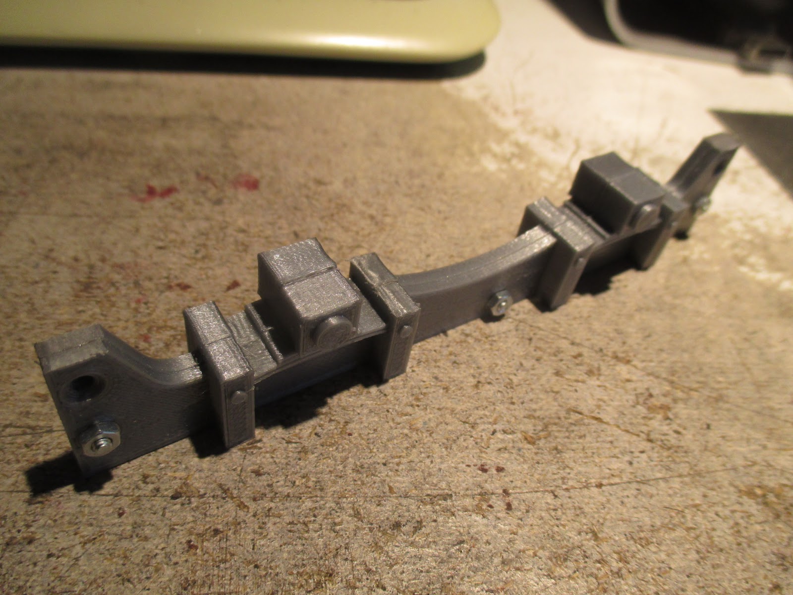
The 3D-printed frames in the kit are a very far cry from that of the prototype. A test assembly with the provided bolts revealed that the extensive stretching of the chassis was to accommodate the motor in it's position between the axles. However, the chassis is lengthened far more than it needs to be - there's roughly ⅝"/16mm of empty space between the rear axle and the end of the motor! I'll have to cut out a chunk of the frames' midsections. Never mind all the other major shape/size discrepancies to fix..
Maybe it's something to do with minimising warpage of the parts during printing; but then I really don't have a clue about such processes.

In any case, these frames can't stay the way they are. I've bolted them together, covering the countersunk holes with tiny washers on this visible side. The round "disks" on the axlebox fronts and on the spring hangers will also be removed, and replaced with more prototypical detailing.
03/08/19
I've never worked with 3D-printed parts before, so I decided to start with a coat of filler primer on the frames, bonnet and whitemetal coupling castings. Three coats (sanding between) later, and the bonnet is smooth. This PLA plastic is surprisingly resilient to sanding, but the bonnet has come up nicely. The couplings also cleaned up nicely.

04/08/19
To work out just how big a chunk had to be taken from the frames, I first had to fit the worm on the motor shaft, and make another dummy assembly run.

The motor's mounting bracket is a nicely-made part, needing only very little cleanup in the center hole, before it could be used.
In the background, a pair of 45mm IP wheelsets was found in the parts box, and the sprockets pushed onto the axles. I wouldn't have been able to make it 4WD on 32mm gauge. A common problem with IP wheels though, is wobbling. In my experience, this is because the nylon insulating bush isn't always drilled concentrically. Swapping out the bush with one from a spare wheel has worked for me in the past, but then I do have a lot of spare IP wheelsets lying about.
In the end, I wound up replacing two of the four bushes - I should've just pressed the un-insulated 32mm wheels off their axles and put them onto 45mm ones. In six years of garden railway modelling, I've only run my models on powered track three or four times, and even then the power was switched off just to be safe.

The motor is fitted to it's mount with self-tapping screws. Normally, this would be a trial-assembly to be taken apart and done permanently later, when I'm ready to install the motor - but I hate self-tappers, so I don't want to touch these particular screws ever again. It's a great idea though, fitting the motor with screws rather than glue - makes it so much easier and less destructive to the model, should the motor or worm ever need replacement. Ideally, one would use a motor with tapped holes in it, for mounting with proper machine screws.

After mocking up and accurately re-checking the length of frame to be cut out, I decided to reshape the ends of the frames, the center spring hanger ends, and add a taper to the sides of the axleboxes. Because the printed PLA material is so hard, I ended using the dremel, which was a bit hairy, as the plastic would rapidly start to melt. I got there in the end, and will finish it with emery boards and needle files after the frames are shortened.
The 3" square and a razor saw made for a good job of shortening the frames.

05/08/19
Rechecking the parts again, and I've under a millimeter of clearance from the rear axle to the motor. Including the saw's kerf, about 16.5mm was removed from the chassis length. The remaining space between the inner spring hangers is still slightly too large, but it's the closest I'll get, and really won't be noticeable.
The fucked-up part, is that the original, unmodified length of the chassis turned out to be a reasonably accurate scale length, in regard to the prototype! So whilst this is now technically well under-scale in length, it somehow looks almost exactly right, even when I check the cab and bonnet dimensions!
So there's a mistake in there, somewhere, either by Mr.IP, myself, or maybe both. But the model looks and seems like it'll work right, so I couldn't care less.

06/08/19
Some ¼" styrene angle was used to join the parts together, taking time to ensure both sides of the frames were precisely identical in length. The holes in the front sides of the axleboxes seem to be cavities in the printed parts, revealed when I removed the un-prototypical "disk" detailing with the dremel.

After etch and filler primers, I could get started on the radiator. There's some blowholes around the bottom of the casting, but that's easy to fill, and the quality is otherwise good. The blowholes were filled with "Selley's Plasti-Bond Bog", and the excess wiped away with a thumb and knife blade.
I quickly realised that the longer I looked at this radiator, the less realistic it became - among many other things, the main issue is that it's thing is a fair bit too wide, as is the bonnet. This isn't much of a problem, though, as I'm thinking that this can be a "might-have-been" 2'6" gauge version, loosely modelled to run on 45mm track. Considering that Hunslet later did an enlarged 2'6" version of the popular 2ft gauge model, I figure what I'm doing sounds reasonably plausible.

Frames bogged up and awaiting sanding.

At this point, I wanted to do yet another mock-up. The bearing holes in the axleboxes needed some careful cleaning out, before the bearings would properly seat. The container of screws was there to counteract the weight of the radiator bending the cardboard "footplate".

08/08/19
The wheels need holes drilling in them. I'd forgotten to measure those of the prototype, so this was just based on photos. Here, I'm scribing out center-lines for drilling, having used permanent marker as marking blue.


Marking the cross-lines was more difficult. Measuring from the front side of the wheel, I decided on 6mm from the flange-tips for the hole locations.


The holes were then started as accurately as I could manage, using a center drill in the drill press..

..Then taking my sweet time drilling through with lubricant, starting with 1.5mm, and working up to 2.5mm.
I did break a couple 1.5mm bits, which is why I keep spares.

The placement didn't turn out perfect (some are just shit) but in this case, it won't be noticeable.

I've finished cleaning up the side frames, using emery boards, (for fingernails) needle files, and for the center arch, the dremel. They're still not as good as I'd like, but it's close enough.
I still don't see why this couldn't have been done properly in the first place..
09/08/19
Cutting the footplate and headstocks from 2mm styrene.

As the chassis went together, thoughts turned to where the batteries and R/C gear will go. I can cram a 14500 lithium-ion cell at either end, (mostly) out of sight behind the headstocks. I've yet to decide where the charging socket will go..

One tiny rolling chassis. Well, almost - the bearings need a fair amount of running in before I fit the motor. A coat of filler-primer should hide the joints and smooth the corners, so the assembly resembles the prototype's one-piece cast chassis.

Even without it's cab and side tanks, a diminutive Accucraft Ruby dwarfs the Hudson Hunslet.

16/10/19
The coupling hooks were fitted, trimmed, and the hooks' shape adjusted with pliers. Rather than the countersunk M2 Phillips screws provided in the kit, I found some spare M1.6 hex bolts in the fasteners container. Their oversized heads are a close match to the cast-in dummy bolt heads, of these very nice coupling castings. A couple of spare IP 30mm wheels were relieved of their axle and blu-tacked to the footplate for extra weight. I don't have a home line right now, so I intended to take the chassis to a club track and couple it behind whatever train I was taking to run there, in order to wear in the chassis' bearings. The day I went, however, was rained-out. I ended up bedding-in the bearings by pushing the chassis back-and-forth along the bench for twenty minutes whilst watching a movie.

I'll trim the bolts when I get to fitting batteries..

10/02/2020
The motor clearance hole was cut in the footplate.

The motor/bracket assembly was used as a guide to drill mounting holes in the footplate.

11/02/20
The motor was fitted with the supplied M2 screws, aligned through trial-and-error, with shims of five-thou styrene.

Testing the gear engagement with a very temporary arrangement involving a Deltang Rx63-2 receiver, and my best friend, Blu-Tac.

That's it for part one. This loco is pretty far down my list of priorities, so further progress in the short to medium term is unlikely.
No comments:
Post a Comment