Over a year since the chassis was assembled. (Fuck you Australian Government, Australian Tax Office and Centrelink, for your fraudulent Robodebts scamming people out of what little money they can scrape up)
Back to the topic at hand, I've finally been able to save enough cash to order the cab and tender kits. (I've decided to initially build the loco with the tender, and possibly make a set of tanks to convert it later on)
I thought some detail additions and modifications were in order, to make this loco more prototypical. In addition to the pony wheels being drilled to match the prototype, a dummy brake cylinder is being made, among other little tweaks.

I realised the Roundhouse model is left-hand drive, while the real B9½ locos were right-hand drive.
Some changes to the reversing linkage were needed to enable the reverser to be fitted to the right side of the cab.
The reversing cranks needed to be unsoldered from their brass hubs, so they could be modified for right-hand drive. I managed to overheat both brass hubs just melting the silver solder holding them together, badly damaging the brass.
My mate Anthony was visiting at the time, using my drill press for his 7/8ths coal-fired loco. He very kindy gave me a spare reversing crank he had. The other hub was replaced by a new one I made on the lathe that evening.

11/09/17
I decided to order the tender kit Without the bogeys; Reason being, I have 3 sets of Roundhouse bogeys, but they're already under other rollingstock.
I've recently acquired 3 sets of bogeys from an old train set so I figured I'd swap the RH bogeys under the open carriage for the trainset ones, and free up those RH ones for use under the tender.
Now, I'd previously bored out the RH bearings to accommodate the Binnie spoked wheels I'd fitted. As I want to keep using the Bnnie wheels on the carriage, and refit the original RH wheels in the RH bogeys, I had to fill in the enlarged bearing holes with soft solder, and redrill them to match the RH wheels' axles.
(Shown here remetalled and remachined, prior to deburring)

The
RH wheels had one hole drilled per wheel, and the holes lined up the
same on both ends of the axles, as per the real B9 tender wheels.

12/09/17
The chassis was reassembled with all the little tweaks and new details.
All the cheese-head screws on the frames have been replaced by hex-head bolts which although still oversize, look better to my eye.When I first assembled the chassis a year ago, I found the thing was just about impossible to turn over by hand. I realised it would have never been able to turn over on air as it was, so this time I spent some more time fettling and towing the chassis around my indoor test loop with a battery loco. The coupling and connecting rods were fitted for this. Even after I fitted the rest of the valve gear, it now turns fairly smooth. Actual running-in under steam will further improve things.
Still a couple little jobs to do yet.


The reversing crank moved to the Right hand side as per prototype.

12/09/17
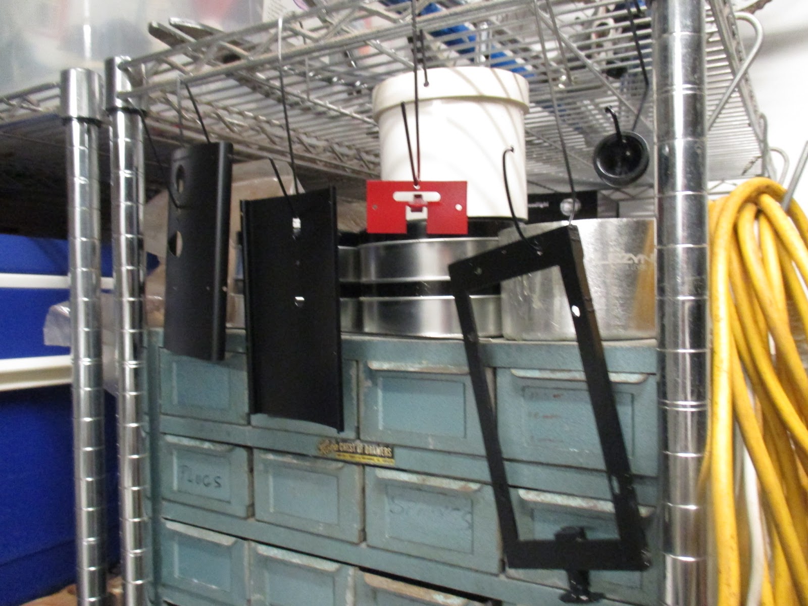
The cab and tender have arrived!

Contents of the tender kit, minus bogeys ($60 saving)

I
also ordered a Darjeeling headlight to fit to the rear of the tender. I
will order another of these with the boiler kit to mount on the
smokebox. Needless to say, they will be functional, with the
batteries/switch in the tender..

Cab kit contents. I'll leave the packet with the domes, etc sealed until I need them once I have the boiler.

I decided to start with the cab, and drill the new mounting holes for the reverser on the right-hand side.
Aside from the round hole in the middle, and the square holes for the roof posts, the rest of the holes seem to be entirely unnecessary for non-RC control, so I needen't worry about duplicating them.

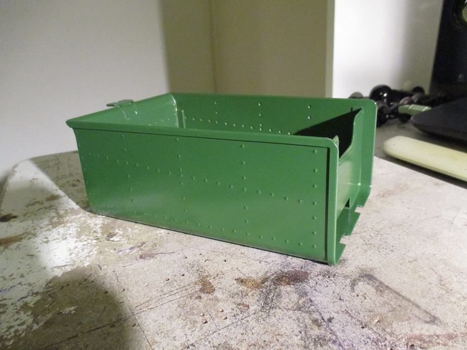
The cab floor/back wall was folded, and while I was at it I did the tender front bulkhead.

Soft soldering in progress. I got away with using el-cheapo bulldog clips, small pliers and a wet rag for all the soldering.

Cab's getting there. Changed out a few cheesehead screws for hexheads on the way.
Some minor filing to remove excess solder, followed by a dip in a citric acid solution to neutralise the flux and clean the metal, and I can give the cab a light coat of primer to check for any areas needing additional finishing prior to paint.

During
a quick 'dry' assembly to check for any possible issues, I found the
coal pile sits too low. Long story short, I might not use the resin coal
load and instead make one from real coal at an appropriate height and
angle relative to the angled line of rivets of the bunker.

After soldering, the tender tank is also ready for the same treatent as the cab..

17/09/17
As I was cleaning up some rogue solder, I realised I'd forgotten to drill a hole in the right-hand side of the cab for the relocated reversing rod, and patch up the old hole. A peice of scrap brass was soldered over the old hole. Looks like some kind of sugar mill repair to me.
The rod itself was also bent to fit and trimmed to length.
The cab was then removed, cleaned and primed.

The middle prong on the rear headlamp bracket was for mounting the ubiquitous British kerosene headlamp.
Like the left-hand drive, this was a modification by Roundhouse to
make the loco more appealing to their home market. Nowt wrong with that
IMO, but I'm doing things differently.
This was cut off, and a mounting hole for the Darjeeling lamp was drilled.
This was cut off, and a mounting hole for the Darjeeling lamp was drilled.

18/09/17
Primer dry, a very small amount of filler was applied to a couple of spots I wan't quite happy with.
The interior was first to be top-coated. This had to be left to harden for several days, so the masking tape won't damage it when I paint the floor and exterior.

After
the tender's primer had cured and spots touched up with filler, I
started spraying the front of the tender, but found the paint was going
on very poorly. I chalked this up to the cool night air, but I don't
normally have issues painting in these normal conditions.. I filled an
old plastic bowl with boiling water, placed a piece of aluminium plate
over it, and the tender body on top, to warm it up. Paint can was
submerged in warm water.

The paint went on far better this time. 1st coat on, another tomorrow once this fully dries.

Rear headlight, tender frame, new loco dragbeam and cab roof all curing.
05/10/17
The cab and tender have been painted and allowed to cure for a few days. As is evident, I missed a spot when masking off the cab interior. This will be fixed after assembly and testing are finished, when the loco gets a final touchup and weathering.
I did get some issues with "fish eyes" in the paint on the cab front, which was quite annoying to fix but I got it sorted in the end..

I was going to buy some "Alclad" chrome paint (which with buffing, actually comes up chrome, unlike most "chrome" paints).
However, Dad suggested tinning the reflector with soft solder and
polishing it. Soft solder doesn't polish very well, but I'm quite
pleased with the result anyway.

The
tender frame, rear coupling and footplate are held together with
self-tappers. The coupling had some lateral movement, due to it's loose
fit with the frame, so it was glued as well as screwed.
At the front, the drawbar engages with a steel crankpin screwed into the tender frame and secured with threadlock.

The tender tank looks a bit plain but has come up well.
M3 screws are inserted through holes in the frame from underneath, and screw into the brass coal support posts.
These were not threadlocked in case the tender ever needed to be dismantled.

The slot in the front bulkhead, intended for the R/C power switch, makes for a very convenient way to control the headlights.
It's a 3-way switch, for front, centre off and rear operation.

Nothing beats the look of a real incandescent lamp. If you've got the battery capacity and heat dissipation, go for it! They can be hard to find though, so don't do what I did and only buy ten..

The reverser in it's correct position as per prototype.


With the cab and tender assembled (though both far from complete) of course it all had to be posed on the indoor test loop.

15/11/17
As the boiler kit alone is about $620 before shipping, I decided to save some money by building the boiler myself. I've done a fair amount of small silver soldering and rebuilt 2 soft soldered brass boilers. That combined with having some great people to advise and assist means I'll have a safe and reliable boiler for cheap - and get to build it.
It's worth noting that I'm building this boiler to comply with the Australian Miniature Boiler Safety Committee code Part 3 - Sub-Miniature Boilers.
Here, I've marked out the centre line of the boiler, so I can drill the holes for bushes in prefect alignment.

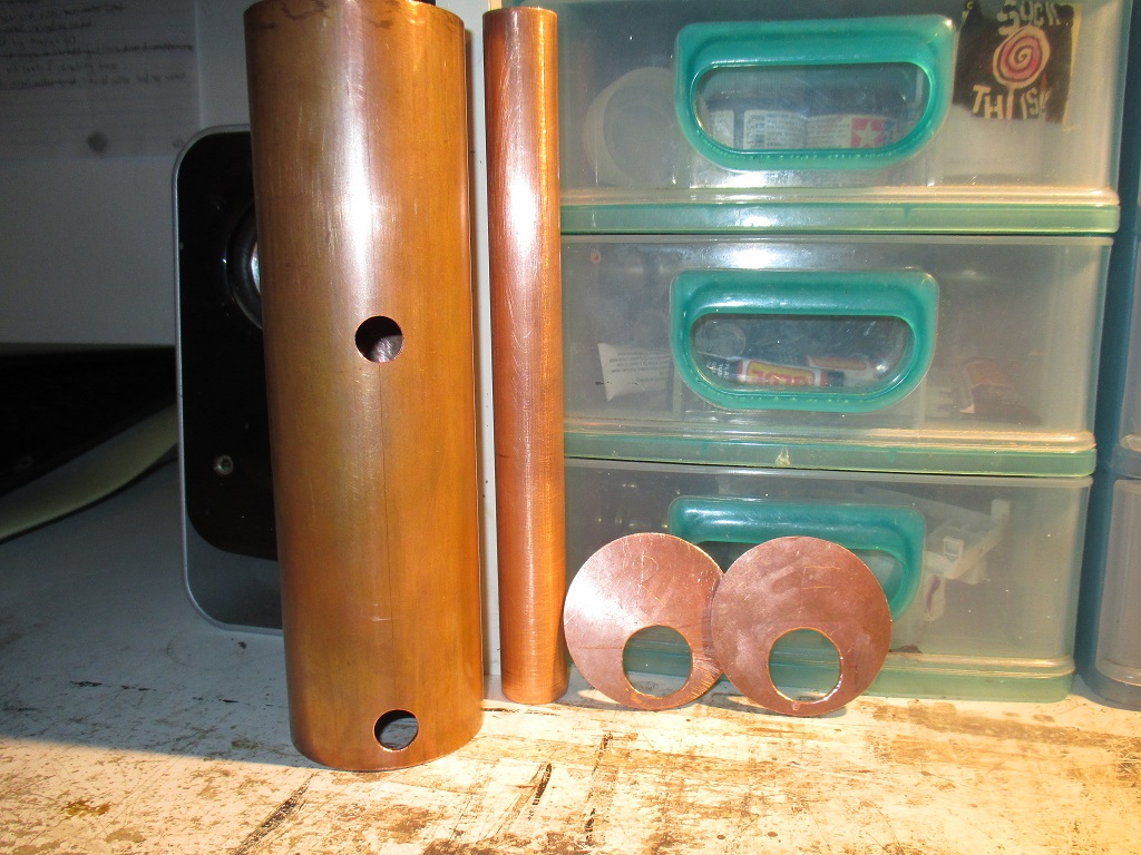
A very generous trade with my mate Glen has provided me with the 2mm copper for the tubeplates, and the firetube itself.
Here, a compass is being used to mark out the circumference of the tubeplates. This conveniently also leaves a mark perfectly in the centre, which helps me to locate the exact spot for the tube hole in each plate.
Here, a compass is being used to mark out the circumference of the tubeplates. This conveniently also leaves a mark perfectly in the centre, which helps me to locate the exact spot for the tube hole in each plate.

A
few hours later, the plates have been cut out and filed to a tight
press fit in the barrel. The tube holes have been marked with the
compass and progressively drilled out until I got to the largest drill
on hand, 10.5mm.
The rest will have to be filed, and finished with a dremel.

16/11/17
Should've taken photos of finishing the tubeplates and drilling the bush holes in the barrel..
The barrel was drilled in the drill press with a piece of hardwood shaped to a snug fit inside, to stop the barrel from bucking under the drilling pressure.
Again, the 10.5mm drill is too small, so when the bushes arrive from Roundhouse, I'll have to dremel out the holes to fit.
Back end.
Building the boiler myself means I can modify the original design. For example, I'm not bothering with a pressure gauge. They play up too frequently and can be wildly inaccurate.
My other loco 'Baron' has never had one and I've learned to run her just fine.
This decision also saves me about $40

Front end.
The firetube is a very slightly loose fit in the tubeplates, because
the dremel took off a lot more material than I expected when finishing
the holes. I'm not entirely happy with that..

The gaps between barrel and plate look bigger than they are.
The following Saturday, I took the boiler parts down to AMRA Zillmere
for boiler inspectors Steve and (can't recall) to check it over before I
get to soldering it all up.
Surprisingly, even with the loose firetube they were very pleased with the work so far.
After checking the club's boiler registration book, they assigned a
registration number for the boiler. The 'rego number is to be permanently affixed
to the boiler.
I also bought a stick of 45% silver solder with cadmium from Steve. Just need the bushes now..
I also bought a stick of 45% silver solder with cadmium from Steve. Just need the bushes now..

23/11/17
Anthony had a Roundhouse safety valve and filler plug going spare, so he kindly gave them to me. Thanks mate, saves me another $35!
This filler plug is drilled and tapped to mount the safety valve in it. I'm not sure if I'll be putting the valve in the cab as standard Fowler practice, or if I'll try and hide it in the plug under the dome, and fit scale dummy valves on top to represent the later modification so often found on Fowler locos..

As the boiler is progressing sooner than I expected, I thought I'd have a closer look at the domes.

Unfortunately,
one of the whitemetal sand dome castings turned out a bit skewed, due
to the halves of the mold not being perfectly aligned during casting.
It's a simple enough fix with filler, but it will be tedious..

30/11/17
The cast coal load has been trimmed to fit the tender. It now sits at an angle to better match the angled line of rivets on the side of the tender tank.
Turns out the coal is a hard plastic, not resin. That's a good thing, as resin is a brittle for my taste.

The new tender hatch parts were made some time ago.

Due
to the way the coal load is angled, the water hatch cast into the coal
is also angled. So it was filed down to a stub and the new more detailed
hatch was glued over the stub, and an angle relative to the coal load
angle, so that when the load is installed, the hatch is vertical.

Now,
when I cleaned up the whitemetal tender frame casting, I wasn't able to
clean up the casting flaws without removing the rivet detail
altogether. I'd hoped the paint would disguise this, but unsurprisingly,
it would require the nuclear option..

So
I filed and dremeled the RH side flat, and measure the location of the
rivets on the LH side, to determine the location for new rivet detail.

Once the first 2 holes were marked out they were started and drilled 1mm deep with the pin vice.
After that, they were drilled another 2mm with the dremel.

With
2 holes drilled, I put drill bits into the holes, and slid a piece of
Veroboard over them, to act as a jig for drilling the remaining 2 holes.
The size of the holes in the Veroboard is 1mm, so I had to drill 1mm holes.

It's not perfect, but it's no worse-aligned than the original cast detail. I believe that tooling dates from the 1980s, but stand to be corrected..
I'm using sewing pins for the rivets, and they have a 0.75mm shaft, so there's a bit of slop in the 1mm holes which helps take out any inaccuracies in my drilling.

One side glued in with shockproof superglue.
The other side was repeated in the same manner, taking measurements from the redone side.

The
coal load was resting on the headlight switch body at the front of the
tender, so I knocked up a quick support for the other side of the
tender, to support the other corner of the load.
The areas of the bunker visible once the load is fitted were painted with Tamiya matt black, brushed on in a vertical direction to simulate soot and coal dust washed down by rain and the slacking hose.

The
burrs on the fall plate were removed with a needle file. I kept
forgetting this part was even in the kit, so it's not been done till
now.
as of writing, it's between coats of paint.
as of writing, it's between coats of paint.

No comments:
Post a Comment