I've already built a steam-era cane train, so now I needed the diesel-era version, like I used to see around Nambour when I was little.
From the late 1960s onwards, hand-cut cane, carried on wholestick trucks were phased out in favour of mechanised harvesting, and transported in steel-framed bins with diesel haulage.So here's what I'm building. Well, something similar, anyway. This particular bin is the last one to be unloaded at Moreton Mill, in the early hours of 03/12/2003. It's now preserved in the Nambour Museum, who kindly allowed me to take measurements of the bin.
Apologies for the poor quality of this photo, there's little space in this shed to get a decent angle.

Over the last few years, I've put a lot of thought into just how I was going to build a rake, of ten bins. I thought about fabricating them from brass or styrene, I thought about casting them from resin or whitemetal. All of those ideas would have been a shitshow of expense and failure for me to attempt.
By sheer chance sometime in 2016, I saw online, a kit for a Moreton cane bin in 16mm (1:19th) scale. Laser-cut from 3mm MDF. Perfect.
The cane bin kit comes with steel wheels with brass bearings. Only thing is, I planned on using curly-spoked wheels from Binnie Engineering, as used on my wholestick trucks and most importantly, the full-size bins. I already had some of these wheels on hand. So I emailed Greg (who makes the kits) to see if I could buy just the bins themselves. He was happy to do that.
I also asked for the dimensions of the bins, so I could make a cardboard mock-up to check that the bins would look right with my existing rollingstock, and clear the layout I still had at the time.
The difference between the 1:19th kit, and my scale of 1:20th was surprisingly large. The mock-up dwarfed everything I have. After a bit of re-scaling of the mock-up, I settled on 1:22. Yeah, that's technically underscale, but it looks right, to my eye, and sometimes in freelance modeling, I think what looks about right, is more important than a number.
So I emailed him back asking if he'd scale the kit down to 1:22 for me. If this weren't a laser-cut item, I wouldn't have asked, of course. With laser-cutting, it's usually relatively simple to re-scale a job. Thankfully this also wasn't a problem. As I was ordering ten bins, I was able to get them a little cheaper still.
After all the accommodations Greg made for me, I felt like a dick - Just as I had got the money together to actually order the kits, some unexpected expenses came up, and left the modelling budget decimated for a few months, so I had to delay the order.
Eventually, I got the money together again and ordered the bins. A little later, I placed an order with Binnie Engineering. Partly to buy some of their excellent Hudson skip wagons, but also to buy the rest of the wheels I needed for the bins. Like the real Moreton bins, wheels are mostly the curly-spoke type, but there's also a few four-hole disk wheels in the mix

10/05/18
I also got enough link-and-pin couplings, and slate wagon axleboxes for the bins. The axleboxes are more like those used on the old wholestick trucks, but they were the they were the closest thing they have, in their packs of eight. In hindsight I probably should've asked if Binnie would sell me forty of their Hudson tipper axleboxes, which are a bit closer to those used on real cane bins..
These castings are yet to be cleaned up.

Let the madness-inducing repetition begin!
The wheels and axles were duly opened and pushed onto the axles. Binnie wheels have a small "pip" on the flange, leftover from the moulding process. It's an annoying job, especially if one doesn't have a lathe, but it's worth removing these pips.
Otherwise, the little bastards find a way to catch on near anything they come into contact with. They may also bottom out in some pointwork and cause derailments. Plus they make a wagon go "thump thump thump" when it's rolled along a flat surface. Fuck that.

Using large and small triangular files, the flanges were cleaned up and rounded off again. This took two hours, but it's still way faster than how I did it before I got the lathe - one wheel on an axle at a time, held in the chuck of an electric drill, which was also held, horizontally in the bench vice.
A Ghetto Lathe it was, so to speak.

29/06/18
The bin frames arrived the other day, so I was eager to get stuck in.
Each bin comes as a flat-pack, complete with flyscreen mesh and templates for cutting it to size.

Just as a laser-kit should be, the parts were very cleanly cut, with virtually no cleanup or sanding to make the parts fit. This bin was just slotted together for the photo.

03/07/18
The chassis is made up of two identical cutouts, each 3mm thick. PVA was applied with a small brush, and the parts tacked with superglue so I can take the clamps off sooner, and move onto the next one. Some of the floor pieces didn't quite align perfectly, which considering the usual accuracy of laser-cutting, was quite annoying. I don't think that was any issue with the quality, rather some expansion and contraction in the various MDF pieces, after they were cut. I live only a mile from the beach, after all.

One way to get better alignment, was to make sure the parts were both facing the same way. This was made easy by the lettering scribed underneath. I don't remember why I made those pen marks on the coupling areas..

04/07/18
As I was using the Binnie couplings, the "dumb" style bumpers were removed with a small hacksaw, trying to cut as close to the frame as possible without damaging it.

Now, MDF is a good material for this job, but it's a bastard to seal for finishing and painting. All the parts needed at least 2 coats of sanding sealer, a shellac-based fluid available at hardware shops.
With all the surfaces to coat, on 10 bins, this was a test for even my patience. At this point, I was wondering if I should've have looked at getting them laser-cut from acrylic..
That's why I always have multiple projects going at any given time. When I get sick of one job, I can take a break from it, and still be productive by getting other work done.

After a couple of coats had soaked in and dried, the remains of the original coupling mounts were sanded away. The bulk of the material was removed on this offcut of timber with coarse emery tape glued to it, made for this job.

Then finished on a piece of 100 grit sandpaper.

This also evens up any difference between the two layers of the chassis, so the sides were also done.

11/07/18
The job of brushing sanding sealer on everything was getting to me, so instead, I laid the bin panels out on timber offcuts and started spray painting them. Initially, I used a pair of cans of green enamel paint that had yellow flecks in it. This was a batch defect, so useless for anything visible, but fine for sealing MDF.
As expected, the MDF really soaks up the thin paint. After 4-5 coats on each panel, I'd just about run out of paint. Only a few panels appeared to be sealed, showing a fairly consistent paint colour. At this point I decided the paint just wasn't thick enough to get the job done.

So I tried some filler-primer I had on hand. Seemed to work much better, and fully cures in less than half the time of the enamel. So I used up the rest of the can sealing what I could. Will have to get more..
At this point, between the enamel, sanding sealer and filler-primer, I had enough panels sealed to assemble a couple of bins and work out where to go from there.

Something I'd not anticipated, but once again obvious in hindsight. Sanding the mismatched chassis panels to match each other resulted in the bin sides overhanging the chassis. Shit, I'll have to build it back up with bog. That however will have to wait until all the bin panels are sealed and assembled.

12/07/18
After buying another can of filler-primer, I could get back to work.
Because I had to spray each panel from so many angles to cover everything, I inevitably found some corners filling up with the filler-primer. The front and back sides of the panel can get a little bumpy from it as well

13/07/18
The corners were cleaned out with needle files, and the sides gently sanded in a figure-8 pattern on the workbench, using 100 grit paper.

Then the remaining bins were then assembled with superglue, as it runs nicely into the seams. The bins were then given one coat of filer-primer and sanded back flat, so as to see just where I'd need to apply bog.

15/07/18
Bins sanded and waiting for bog.

17/07/18
The bog (a two-part fibreglass mix) was applied with a flat-blade screwdriver. The joints between panels were also filled. This stuff stinks, so the windows were all open and the fan was on. As was a jumper, on me. Middle of Winter here, and all that.

18/07/18
After sanding back flush with the frames, it looks far better. There's still small spots needing another hit with bog, all over the bins.

19/07/18
Second and final coat going on.

24/07/18
After sanding back the second coat of bog, the bins got another thin coat of filler-primer to fill in any sanding marks. Then I figured I better get onto detailing.
I would've liked to have scribed joint lines between the panels, but previous experience tells me the surrounding paint tends to chip quite badly, no matter how lightly the scribe is passed over. So unfortunately I'll have to leave that out.
As you can see on the prototype, the bins are fabricated as separate panels, then bolted together through these "tabs". Makes construction, repair and replacement of damaged panels relatively quick and easy.

The chassis of the bin, (top) is on each side, about half an inch wider and longer than the bin itself.

To model the tabs and larger chassis, I'm using styrene. After measuring the full-size parts and scaling them down, I've made a jig for cutting them all, once again from scrap wood, and coffee stirrers.

These wider chassis strips were cut from a sheet of 0.5mm material bought for the job. The knife blade was extended further than usual from the knife body, and rocked back and forth over the strip. This way, I get nice, square cuts with virtually no cleanup required.

The blade is the type that one snaps off sections of as they go blunt. This blade was getting short, and the rocking motion of the cut was starting to deform the knife's plastic body. So I replaced the blade with a fresh, long one, so the forces would be more evenly distributed along the handle of the knife.

For the tabs, I was going to cut 3mm wide strips from the larger sheet, but thought I'd better try to preserve what sanity I have left, and just bought a packet of pre-cut 3mm strips.
Cutting them was done with the back end of the short blade taken out of the knife, which would have been a shame not to use, as it was effectively brand new.

The tabs are in two lengths.

Overall, there are 120 short tabs, and 160 long ones. When I make small parts in large quantities, I arrange them in stacks of 10, 20, 50 etc. to keep track of how many I've made. Otherwise, I'm just constantly forgetting, losing count and recounting everything.

06/08/18
Upon final inspection prior to fitting the styrene parts, some minor surface imperfections were found and sanded back. Over the course of all this sanding and recoating, the sides of the holes in the bins have also been needing sanding. This has been a real annoying job, requiring small emery sticks made for filing fingernails. I buy packs of them from cheap shops.

Another light coat of filler-primer to smooth out any sanding marks..

..And the job of sealing, gapfilling and finishing the bins is finally over. Thank fuck for that.

07/08/18
With the bin frames done, I can start detailing. The chassis strips are added first, again using superglue.

The corners are gently rounded a little with an emery stick.

One of the bins was subject to an early experiment in chipped paint effects. It will be painted over, and the chipping effect done after the main painting. Under the workbench light, a couple other bins were found to still have slight imperfections, so were sanded yet again. Last time, I promise.

08/08/18
The tabs were fitted using a fine-tip applicator that slips over the end of the superglue tube. There's no way I could've glued neatly without it. You can buy packs of them cheaply on Evilbay.

The Binnie couplings were pretty rough castings, very unusual for Binnie parts, in my experience. After having fitted the couplings, one can see just how much bog and filler-primer was needed on them. They're good now, though.

09/08/18
I forgot to photograph painting the Binnie parts when I got them, but here I'm testing possible locations for them. The axleboxes are temporarily held to the chassis with blu-tac.

Unfortunately in 1:22 scale, the solebars of the chassis are just a few millimeters too close to each other to allow for 45mm gauge. The wheelsets do fit between the solebars, but only just, with no room for the top "angle" bit of the axleboxes. On 32mm gauge, it'd all be fine. So the top "angle" bit had to be removed with the dremel, so the axleboxes could be fitted flush with the bottom of the frames.

10/08/18
The original axlebox mounting slots had to be filled in to make a good footing for the axleboxes. Some sections of the frames also had to be cut out to clear the wheels. Masking tape was used to keep any errant filler away from the outer sides..

At first, I used the blade from my small hacksaw, but this was making my hand ache and was horribly slow. Over all the bins, there's 80 of these cuts. So I decided to dig through one of the boxes I had packed away for moving house, to find a circular saw blade for the dremel.
I'd originally bought the blade for a live steam sawmill project a couple years ago, but have yet to get started building it. I think I'll keep this blade for the dremel, as it worked really nicely, and buy another for the sawmill when that eventually happens.. But I'm rambling way off-topic again.
The dremel was then used to clean up the cut areas and the filler around the slots.
As is evident, the joint between the two layers of the chassis is quite visible. I did what I could with the filler-primer, but even then I'm not going to sand all that flat. Instead, I'll hide half of it..

I'd always intended to deviate from Moreton practice, and cover the center of the bin's floors with corrugated sheet. The original intention of this was to conceal lead weight under the chassis, if extra weight is found to be needed. Literally speaking, the tin also hides half of the join lines in the chassis layers. It also hides those sections I cut out to clear the wheels.
Here, I've corrugated a piece of aluminium roof flashing in my home-built roller. The 'ally sheet was originally 70mm long, which was an educated guess. 70mm is too long to begin with, but as one loses some length to the corrugations, one has to compensate.

The home-built corrugating roller, using the aluminium rollers from a Fiskars paper crimper, running in bronze bearings machined on the lathe. The frame as you can see, is made of spare timber. The vice-grips handle is semi-temporary. The material, a roll of 0.3mm aluminium roof flashing, (available from hardware shops) is in the background

70mm wide was very close, but still too wide. 68 was right. So I cut the first piece of sheet, double-checked the fit, (it was good) then wrote the size on the sheet and blu-tacked it on the desk in front of me. Otherwise, I wouldn't have remembered the exact dimensions.

Permanent marker was used to roughly mark out where the sheet was to be cut.

Then, using a try-square, a couple steel rulers and a dull blade in the Stanley knife, the exact locations for cutting were marked out.

After cutting out ten sheets with scissors, the permanent marker had to be removed. Otherwise, the paint won't stick to the metal. Alcohol, meths or thinners will make short work of "permanent" marker.

The sheets were then passed through the roller, and test fitted. All good.

I then started cutting out the flyscreen mesh to fit the bins, using the supplied templates and a lot of care, to make sure the cuts are straight and square with the pattern of the mesh.

Two hours later, the mesh is ready for paint.

12/08/18
After etch priming the corrugated sheets, I realised the real sheets are getting pounded by dozens of tons of sugarcane, day in, day out. So after some abuse from a cold chisel and a large brass drift, they were sprayed with the red oxide topcoat.

I sprayed one bin to see how this red oxide primer looked. I also painted most of a mesh panel to get an idea for what shade of grey to use.

After the fist bin, I realised the fullsize wheelsets and axleboxes would've been painted along with the bins, so I fitted the running gear prior to painting.

By the time I got around to painting, it was night, and getting cold. So having learned the hard way not to paint in poor light, I set up a couple extra lamps by the garage doorway.
The bins' wheels were blu-tacked to some scrap MDF, so I could paint several bins at once.
Although the nozzle on this can of paint is identical to those of the other spray cans, it's extremely hard to press. And there's not really enough pressure coming out of the can. This is a problem. Not only is this thing physically painful to spray, but when there's little pressure to propel the paint, the paint tends to splatter onto the work - rather than a nice, fine, even spray. I've never had a can behave like this, not even in colder weather. Changing the nozzle out helped a little, but not much. A little more effective, was preheating the can in very hot water, and shaking frequently to raise the can's internal pressure. With this, I was just able to scrape by.

04/09/18
The mesh took a while to paint. Initially, I sprayed one with enamel grey primer. It wouldn't dry. Some research revealed that ordinary flyscreen like this, is made of fibreglass, then coated with PVC. Enamel paints, and most types of PVC, don't mix well.
So I had to make up an acrylic mix. That's fine, as I was able to make a better colour with acrylics anyway. I airbrushed a few panels, but what with having to manually turn the compressor on and off every couple of minutes, made airbrushing no faster than handpainting. With the brush, the mesh panels needed two coats on either side. The photo makes the colour just look grey, and it is, but there's a tinge of brown in there, too. Makes it look like well-oxidised and dirty galvanised mesh. Well, I reckon it does, anyway.

Now to start weathering. After looking into various methods of simulating chipped or peeling paint, I went with the sponge method. This is similar to dry-brushing.
First, tear off a piece of sponge and lightly dip it into some paint. I mixed some up just for this job. A palette, paint jar lid or small tray is good for this. I just used the jar lid, and later, applied the paint to the sponge with a brush.

Most of the paint is dabbed onto a paper towel, leaving just a little left on the sponge.

The sponge is then gently dabbed onto the model, leaving tiny flecks of paint. If done correctly (and it's very easy to overdo) it should look very much like a painted surface, with rust spots where the paint has peeled, chipped or worn away, exposing the underlying steel to the elements.

As I just said, it is all to easy to overdo, but being acrylic paint, it's easy to wipe away mistakes while they're wet.
I do wish I'd applied it more to the edges and corners, rather than just the sides. You know, where the paint actually wears off? I got 4 of the bins done like this before I got sick of doing it.
I also really shouldn't have done it so heavily, as I'm modelling bins of only 5-15 years old. They're not supposed to be as chipped and rusty as the bins at the Nambour Museum, which saw service for around 30 years. At this point, I'm just gonna make up a backstory to explain why bins of only 5-15 years old are so badly chipped: "Some apprentice painted those bins, but did fuck-all surface prep before painting, so now, a few years later, half the paint's falling off."
Great. Now I can sleep at night.

05/09/18
I glued the mesh and corrugated tin into one of the bins before doing the chipping treatment. The camera couldn't make out the difference in colour between the rust and red oxide when I tried to photograph indoors, so I brought the bins outside. Another reason for this was even with the desk lamp, I couldn't really see just how heavily I was applying the rust, so I figured for a subtle job on the rest of the bins, using the lighting these things will normally operate in, would be better.
I also fitted coupling hooks to this bin, made from modified picture hooks. The process is covered in the tipper wagon build, about ⅔ down. Glued them in using JB Weld.

The mesh was also given a little of the sponge rust treatment, in addition to the corrugated sheet. I'm pretty happy with it all so far.

As we no longer have a card table, something temporary had to be knocked up from what was at hand.

The bolt holes in the Binnie couplings looked a bit odd for a wagon which would've had it's couplings welded on, so I drilled through the couplings' holes and through the wagons' frames.

The holes were then plugged by gluing in some spare flat-head nails. The nails were painted, chipped and cut short before fitting. Still looks odd to me, but less so now, and adds some much-needed mechanical reinforcement to the coupling mounts. It'll do me.

I do wish I'd applied it more to the edges and corners, rather than just the sides. You know, where the paint actually wears off? I got 4 of the bins done like this before I got sick of doing it.
I also really shouldn't have done it so heavily, as I'm modelling bins of only 5-15 years old. They're not supposed to be as chipped and rusty as the bins at the Nambour Museum, which saw service for around 30 years. At this point, I'm just gonna make up a backstory to explain why bins of only 5-15 years old are so badly chipped: "Some apprentice painted those bins, but did fuck-all surface prep before painting, so now, a few years later, half the paint's falling off."
Great. Now I can sleep at night.

05/09/18
I glued the mesh and corrugated tin into one of the bins before doing the chipping treatment. The camera couldn't make out the difference in colour between the rust and red oxide when I tried to photograph indoors, so I brought the bins outside. Another reason for this was even with the desk lamp, I couldn't really see just how heavily I was applying the rust, so I figured for a subtle job on the rest of the bins, using the lighting these things will normally operate in, would be better.
I also fitted coupling hooks to this bin, made from modified picture hooks. The process is covered in the tipper wagon build, about ⅔ down. Glued them in using JB Weld.

The mesh was also given a little of the sponge rust treatment, in addition to the corrugated sheet. I'm pretty happy with it all so far.

As we no longer have a card table, something temporary had to be knocked up from what was at hand.

The bolt holes in the Binnie couplings looked a bit odd for a wagon which would've had it's couplings welded on, so I drilled through the couplings' holes and through the wagons' frames.

The holes were then plugged by gluing in some spare flat-head nails. The nails were painted, chipped and cut short before fitting. Still looks odd to me, but less so now, and adds some much-needed mechanical reinforcement to the coupling mounts. It'll do me.

11/09/18
I'm planning an event for the beginning of December 2018, to commemorate 15 years since the closure of Moreton Sugar Mill in Nambour. This will require the cane bins, and the Baguley diesel (still in the works) to pull them, 60 yards of handlaid track I'm in the process of building, A full day or two of site preparation, my wholestick trucks, and both of my live steam locos. (the one in the photo, "Victoria" isn't complete yet either)
Throw in a house move in eleven days time, and you've got a bit of a clusterfuck..
As such, multitasking and more importantly, putting all my free time into these projects, is the only way I'm gonna get it all done in time.
As I keep an eye on "Victoria" pottering around some Newqida plastic track on a running-in turn, I'm also cutting out the number boards for the bins, from spare styrene cut for the chassis detailing. The table saw makes a decent temporary workbench. I'd prefer to do all this at my desk, but I don't have a rolling road for the loco, nor the money to buy, or time to build one. So this'll do for now.

12/09/18
Now the bins are painted and chipped, the mesh can go in. Using superglue applied through a fine-tip applicator, I work in sections, starting with the bottom half of the frame.

After carefully placing the mesh panel in, and pressing it down with a flat-blade screwdriver, the process is repeated for the top half.

After drying for a minute, sections are reinforced with spots of glue, which flows into the mesh quite nicely.

13/09/18
I'm thinking I'll make most of the bins permanently coupled together with solid drawbars, like I did with the wholestick trucks, considering I'll generally run these as a single rake. It's just less fiddling with little chains and pliers.
The pin hole in the couplings is enlarged with a 2.5mm bit in the pin-vice.

Then tapped M3.

Of course I'll need drawbars. Initially, to avoid having to find suitable metal sheet and go drill and file it into little drawbars, I made a couple of simple hoops from spring wire, with soft-soldered joints.

A few minute's testing however, showed me these wouldn't really do the job I wanted. Well shit, I'll have to do it properly then.

A few hours later, I had five little drawbars of 0.6mm aluminium from the scrap box. A bit rough, sure, but they'll barely be visible, and precious time is best spent where it really matters.

Fitted with temporary screws here, the solid drawbars work much better then the wire loops.

The real Moreton bins' numberplates looked like this after 30 years of use and abuse. I'll be going for something a bit less decrepit. I'm guessing the placard holder on the right is for identifying which farm the bin came from, and is to be delivered. The left plate is so knackered I've no clue.

I was hoping (but not holding my breath) to make use of the cheap yellow spray paint I had spare. The camera doesn't really show it well. It's more of a fluorescent shade, much too bright, even when misted over with flat white. I'll have to buy some Tamiya stuff just for this.

27/09/18
House move was five days ago, and despite the new works not being fully established, I can finally get back to work and try to make up for lost time.
The coupling parts have been cleaned and mounted to a piece of scrap timber for painting.

30/09/18
A comparison of the standard 1:19 bin mock-up with my 1:22 version, and the Baguley in it's later stage of rebuilding. Somehow I doubt the Accucraft Baguley is quite 16mm scale. But I don't really care enough to find out for sure.

01/10/18
Some Tamiya flat yellow was mixed in a jar lid with some black, white and a touch of brown, then applied with the airbrush - after replacing the regulator on my compressor. Another time-consuming job.

The result is well worth the trouble though.

03/10/18
The coupling parts have been painted, fitted and given the chipping treatment in-situ. A little additional chipping was done on all of the bins at the same time.

Of course, the bins need loads, and I want them removable. I'm not building a two rakes, one loaded and one empty. The only removable, good-looking method I can think of is doing it the hard way - with thousands of tiny loose billets.
So I thought I'd make a start on filling the bins. An extremely time-consuming job, and quite painful after a while. Getting just one bin 4/5ths full took four hours. I think I'll make some styrofoam inserts to fill the majority of the bins' volume, leaving say a 3/8" gap between the foam and bin frame, to fill in with the billets. Even so, it'll be a really horrible job, one that I think will wait until after the December event, as it's really not essential.
The tiny billets fall out of the mesh just as much as they do in fullsize. Realistic and looks great, but gets messy pretty quick. A mixed bag of a method, so to speak.

House move was five days ago, and despite the new works not being fully established, I can finally get back to work and try to make up for lost time.
The coupling parts have been cleaned and mounted to a piece of scrap timber for painting.

30/09/18
A comparison of the standard 1:19 bin mock-up with my 1:22 version, and the Baguley in it's later stage of rebuilding. Somehow I doubt the Accucraft Baguley is quite 16mm scale. But I don't really care enough to find out for sure.

01/10/18
Some Tamiya flat yellow was mixed in a jar lid with some black, white and a touch of brown, then applied with the airbrush - after replacing the regulator on my compressor. Another time-consuming job.

The result is well worth the trouble though.

03/10/18
The coupling parts have been painted, fitted and given the chipping treatment in-situ. A little additional chipping was done on all of the bins at the same time.

Of course, the bins need loads, and I want them removable. I'm not building a two rakes, one loaded and one empty. The only removable, good-looking method I can think of is doing it the hard way - with thousands of tiny loose billets.
So I thought I'd make a start on filling the bins. An extremely time-consuming job, and quite painful after a while. Getting just one bin 4/5ths full took four hours. I think I'll make some styrofoam inserts to fill the majority of the bins' volume, leaving say a 3/8" gap between the foam and bin frame, to fill in with the billets. Even so, it'll be a really horrible job, one that I think will wait until after the December event, as it's really not essential.
The tiny billets fall out of the mesh just as much as they do in fullsize. Realistic and looks great, but gets messy pretty quick. A mixed bag of a method, so to speak.

Sick of cutting cane, I decided to start cutting lead.
After measuring the spaces under a bin frame, The lead was marked and cut in a similar fashion to how I did with the aluminium sheet earlier on.

The lead was stuck on with KS Bond. Good stuff, I know from experience the lead will never fall off on it's own.

Two layers of the longer pieces between the wheels, and four layers in the middle section bring the bin's weight from 93g to 208g. Can't see them flying off the track any time soon, given the driver isn't a speed freak.

04/10/18
The backsides of the numberplates were painted with the same dirty galvanised-colour paint mix I used on the mesh. The camera however, just makes it look plain grey. I guess from any distance over eight inches away, it's just gonna just look grey anyway.

07/10/18
Something I've been meaning to do on all my rollingstock, is airbrush the wheels a dirty tan colour. On most of 2ft gauge wagons I've seen, the wheels and axleboxes are generally caked with this dry mixture of dirt, mud and oil that has set rock hard over time.
I've not yet attempted to model this, so these bins will be the guinea pigs. After mixing and thinning the right colour, any visible parts of the undercarriage were moderately sprayed, leaving the odd spot of red oxide showing through. A little "dusting" was applied around the bottom sides of the chassis as well.

08/10/18
After the "grime cake" weathering had dried overnight, the bins were all given a thorough clearcoating with Tamiya flat clear. Lucky I bought two cans for this job, I used them both up completing it.
The 3" brush was to remove any dust caught in the mesh, prior to spraying.

There was a few days delay waiting for the number decals to arrive in the post due to a public holiday the week before. So as soon as they arrived I got straight into applying them.

09/10/18
All but one of the numbers, are various works or running numbers of fullsize locos, that came to mind. When I took this photo, I didn't realise I'd only applied the numbers to nine of the ten pairs of numberplates. The last pair was then done.

After a light coat of Tamiya flat clear, a very thin "dirty" wash was mixed up and applied to tone the plates down a bit.

The second part of the running gear weathering, was the oil-soaked bits, namely the bottom of the axleboxes and the wheel hubs. A dark grey wash was mixed up, with some gloss clear in it to give it a hint of shine, simulating oily wet patches. Well, greasy bits, in the case of cane bins anyway.
I could've applied it with the airbrush, but by now I was sick to death of cleaning the fucking thing all the time, and I don't want to annoy the neighbors with the compressor on my verandah. So two coats done the old way won out, and the appearance is better for it, in my book.
I'm extremely happy with how the running gear weathering has turned out, and will not only apply it to every other wagon I currently have, but to every wagon I build or buy frome here onward.

Numberplates fitted with superglue.

Then a little flat clear was brushed on the backside, to hide the superglue's glossy finish.

11/10/18
The remaining coupling hooks are fitted with JB Weld and allowed to set for a few hours.

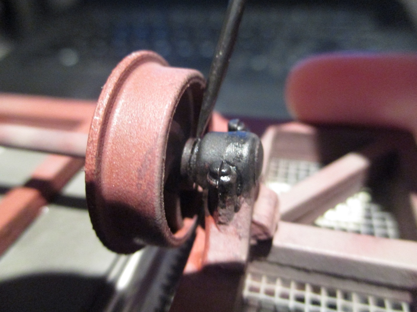
The axleboxes were then sparingly lubricated with a small screwdriver dipped in 20-50 engine oil, thinned with a few drops of light machine oil. This allows the engine oil to wick into the bearing instead of oozing all over the place. I've found the lighter oil tends to evaporate over a few months, leaving the thicker oil to do its job.

12/10/18
Again combining jobs. Seven of the ten bins are given a test run with "Victoria", which having clocked up 9hrs in either direction as light engine, and now well run-in, was finally pulling her first train.
Most of the bins are quite stiff running, due to the modifications to the axleboxes' mounts, making the axleboxes and axles themselves not perfectly aligned. The loco's regulator had to be fully open and the safety lifting constantly just to keep the seven bins moving on the tightly-curved test track. The loco couldn't move all ten on this track.
The bins' bearings will require a lot of running in to correct. Other than that, they seem fine. A proper test run on a proper track will really make sure they're good runners.

The remaining coupling hooks are fitted with JB Weld and allowed to set for a few hours.

The axleboxes were then sparingly lubricated with a small screwdriver dipped in 20-50 engine oil, thinned with a few drops of light machine oil. This allows the engine oil to wick into the bearing instead of oozing all over the place. I've found the lighter oil tends to evaporate over a few months, leaving the thicker oil to do its job.
12/10/18
Again combining jobs. Seven of the ten bins are given a test run with "Victoria", which having clocked up 9hrs in either direction as light engine, and now well run-in, was finally pulling her first train.
Most of the bins are quite stiff running, due to the modifications to the axleboxes' mounts, making the axleboxes and axles themselves not perfectly aligned. The loco's regulator had to be fully open and the safety lifting constantly just to keep the seven bins moving on the tightly-curved test track. The loco couldn't move all ten on this track.
The bins' bearings will require a lot of running in to correct. Other than that, they seem fine. A proper test run on a proper track will really make sure they're good runners.

14/10/18
All the bins that weren't permanently coupled, needed some suitable-length coupling links.
I took some floral wire and twisted it around a suitably-sized tap, then cut off fourteen rings. It took some trial and error to find the right size of ring/link, so that with two links, the bins would be coupled together with the same distance between them as the permanently-coupled bins.

The rings were then cleaned in citric acid for a few hours, the joints silver soldered, then blackened in the usual way. The hook on the left is for "Victoria", blackened at the same time.

19/10/18
There's an open day at AMRA Zillmere tomorrow, where there's a dual 32/45mm gauge elevated track. An ideal place for a test run, considering I don't yet have a railway at this new house. Now as I don't drive a car, I must rely on public transport, carrying any locos and stock in a wheely bag. Therefore everything must be very well packed.
I was running out of time, so a semi-permanent solution was thrown together. A box leftover from the move was found to be a tight fit, but serviceable. The fixed rakes of three bins just fit, but they must be arranged zig-zagged, such as they can be, to fit.

A layer of cardboard protects the bottom bins' paint from damage, so more bins can be stacked on them. I've been stockpiling styrofoam for a future HO layout, so I cut some to fit with my hot knife.(A cheap kitchen knife, the blade heated with a small butane torch)

Having an extra two bins to fill the excess space, sounds great right about now. Some more foam is a good enough substitute. Some plastic shopping bags were also packed in case it rains tomorrow, and I need to cover things quickly. I usually use a disposable plastic drop sheet, but I keep forgetting to replenish my depleted stock of 'em.

The top piece was at some point used as a template in my stalled sawmill project. A crescent shape was cut out to make removing the foam easier.

All the bins that weren't permanently coupled, needed some suitable-length coupling links.
I took some floral wire and twisted it around a suitably-sized tap, then cut off fourteen rings. It took some trial and error to find the right size of ring/link, so that with two links, the bins would be coupled together with the same distance between them as the permanently-coupled bins.

The rings were then cleaned in citric acid for a few hours, the joints silver soldered, then blackened in the usual way. The hook on the left is for "Victoria", blackened at the same time.

19/10/18
There's an open day at AMRA Zillmere tomorrow, where there's a dual 32/45mm gauge elevated track. An ideal place for a test run, considering I don't yet have a railway at this new house. Now as I don't drive a car, I must rely on public transport, carrying any locos and stock in a wheely bag. Therefore everything must be very well packed.
I was running out of time, so a semi-permanent solution was thrown together. A box leftover from the move was found to be a tight fit, but serviceable. The fixed rakes of three bins just fit, but they must be arranged zig-zagged, such as they can be, to fit.

A layer of cardboard protects the bottom bins' paint from damage, so more bins can be stacked on them. I've been stockpiling styrofoam for a future HO layout, so I cut some to fit with my hot knife.(A cheap kitchen knife, the blade heated with a small butane torch)

Having an extra two bins to fill the excess space, sounds great right about now. Some more foam is a good enough substitute. Some plastic shopping bags were also packed in case it rains tomorrow, and I need to cover things quickly. I usually use a disposable plastic drop sheet, but I keep forgetting to replenish my depleted stock of 'em.

The top piece was at some point used as a template in my stalled sawmill project. A crescent shape was cut out to make removing the foam easier.

20/10/18
The bins were tested with "Victoria" on the Zillmere track. Both did quite well, with the loco well able to pull the full rake around the large curves. The bins' bearings are noticeably better-rolling after about 90 minutes of running. "Victoria" needs a few minor things done, but the bins just need running in, some loads, and entering into the rollingstock list.
Adding the bins to the loco/stock list is a fairly quick job, and well worth doing. This way, I can keep track of when things entered service, what mods I'd done to them, any attention they need, and all that.

Some ex-works shots, posed with the Baguley diesel which will be the bins' usual motive power. The loco still needs some minor work at this stage, but is virtually complete.
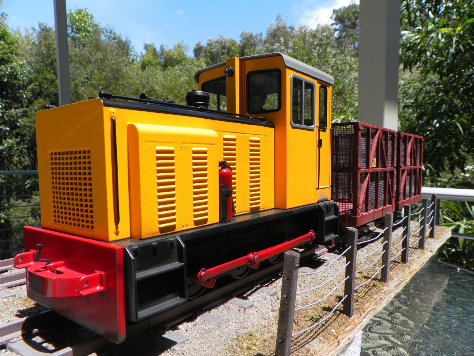
I think for a Moreton-style freelance 1970s cane train, this'll do me pretty well. Just need to cut up a stack of millet brooms when I get the time and energy, which is looking like next year, as there's still a lot to do the event in December..

If you're looking to build a rake of bins, then I highly recommend these kits.
Thanks for reading, I hope it was of use.
Thanks for reading, I hope it was of use.


