A change in circumstance means unfortunately, I most likely won't be living anywhere permanent for the next 2-3 years - That almost certainly means no new garden railway in that time.
I've decided to focus on rollingstock and structure projects in the meantime. This will also help expedite the process of planning the new railway..
One thing I'd like to do eventually, is to incorporate a street running section of track, as once seen on the cane tramways of Moreton Mill, and as continues today at Mossman Mill.
A prominent feature of such scenes, is often the ubiquitous timber Australian corner hotel & pub - So I guess I'll start with one of these.
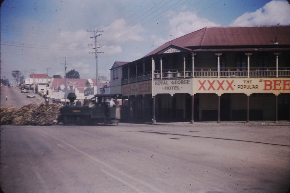
This pub stood on the corner of Howard and Currie streets in Nambour, Queensland, from 1903 until it burned down in 1961. This excellent 1935 photograph, along with a (very) few others like this one, will be my main two references - though my pub will only be based on the Royal George, rather than a scale replica.
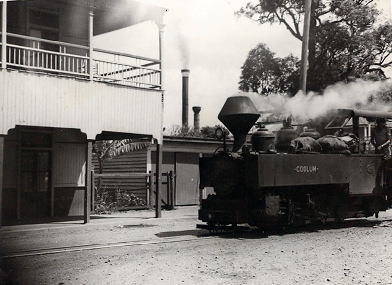
The cane tramway ran very closely past the pub, the rails being visible just below the car. The wide, overhanging cane loads often brushed the verandah posts as they passed. Later on, the line was relaid closer to the middle of the street, to help reduce congestion problems with increasing road traffic. Later still, after the pub burned, the line was again relaid, this time in the centre of the street where it remains today.

21/03/2019
The eventual garden railway will be designed/built with ease of use as it's highest priority. Therefore, as many of the buildings on it as possible, must be weatherproof, so I don't have to set them out and bring them in every time I want to have a run. So as a rule, I'm trying to avoid any and all timber or paper in buildings.
I've seen quite a few very nice buildings being made from PVC foamboard (also known as Foamex or Sintra), mostly by British modelers. From what I've heard, it's light, fairly cheap, easy to work, and most importantly - weatherproof. I started familiarising myself with the material, by making a small, simple "weatherboard" shed. It turned out well, so I got stuck into designing the pub.
Using my Roundhouse Fowler "Victoria", a 1:24 car, a figure, and photographs of cane trams in Nambour, I started working out the rough size and dimensions. I found it simpler to work with Imperial dimensions, for this job.
Considering the emerging design was nearly entirely Imperial, I figured "Imperial Hotel" would be as good a name for the building, as any.

Comparing the drawing to to the 1935 photo, you'll notice the shorter leg of the building is a little shorter than the prototype. This is simply to cut down on some work, and to make this already huge building a little less bulky. The angle of the prototype's front walls was about 105 degrees. I've changed this to 90 degrees, simply to make it easier to build.

25/03/19
Dimensions at hand, I started by cutting out the main front and end walls from foamboard. A scrap piece of aluminium angle was checked for straightness, then used as a straight-edge for marking and cutting. 2-4 passes with a hobby knife cuts the foamboard nicely.
I'm cutting the foamboard on my balcony, as it's a 3x4ft sheet, and it's the only suitably large, hard flat area available. Needless to say, a great deal of care was needed to ensure the knife didn't cut into the decking boards. Although the blade never touched the deck, a sacrificial sheet of plywood or MDF between the foamboard and deck, would've made things far quicker and easier.

The main wall sections were then mocked up, held together with masking tape. I can't make the rear walls or the base yet, as the shop was out of corflute. The angled front wall will be made to fit, once the other walls are assembled on the base.

27/03/19
I'm going to need a lot of styrene sheet for this and future buildings, and most of the time here in Australia, it's prohibitively expensive. I was able to find a local plastics supplier on Evilbay, and bought five A3-sized sheets of 1mm thick styrene for just $20.
It's quite shiny on one side. Too shiny, this could be a problem for paint and glue adhesion.

Much better after a quick wet sanding with 400 grit wet-and-dry sandpaper.

Now to get on with the vertical-boarded fascia, that hangs down from the verandah.
(I've no idea what the fascia's correct term is)
I cut some 3" wide strips from the styrene sheet, long enough to run the length of the verandahs.
Despite it's overall dimensions in Imperial, the width of the fascia's boards is one of the few things I'll be doing in Metric. 5mm looks about right to me.
A sharp pencil was used to mark out the board spacing along the length of the fascia sections.
The marking process was repeated along the bottom edge.

A steel ruler was aligned with the aforementioned pencil marks at the top and bottom of the styrene, and held in place. 6" and 4" flathead screwdrivers, and the knife, were carefully used to scribe grooves in the styrene, using the ruler as a guide. The surface was then cleaned up with 800 grit sandpaper.
You'll notice the odd wandering, errant line: It's all to easy to slip and wind up scribing where you don't want to. I'm hoping it won't be too noticeable once all is finished.
Unsurprisingly, scribing has caused the styrene to bow outwards. Annoying, but it'll be getting substantial reinforcing framework to support it in any case.

28/03/19
It's an awfully slow process, scribing styrene, but the front faces of the fascia are done, and the cut-outs, well, cut out.

To save a lot of time, effort and frustration, I made a styrene stencil for marking out the doors on the foamboard walls.

After marking out the door itself, a frame was drawn up to surround it. The frame is ¼" thick, with a ½" tall fanlight window above the door.

After working out the correct spacing based loosely on my reference photos, the remaining doors were marked out. The frames and lower paneling in each door were then scribed with the screwdrivers and ruler, similarly to the styrene fascia. Foamboard is much easier to scribe - a pleasure, actually.
You'll notice on the left, I got carried away and started scribing the vertical boards, before remembering to get this shot.

A ruler and knife were carefully used to cut the windows from the doors.

The openings were then cleaned up with emery boards. These are made for filing fingernails, but are excellent for modelling. I get mine at discount shops or supermarkets. They're easily cut down to fit smaller spaces, as I've done here.

The windows were time-consuming to do, but came up well. The vertical boards can now be finished.

They were marked out in the same manner as the fascia. Again, 5mm width, as it looks about right to my eye, and is easy to mark out.

Holding the ruler firmly in place, the 6" screwdriver scribes the boards. Moderate pressure applied over a single pass is sufficient.

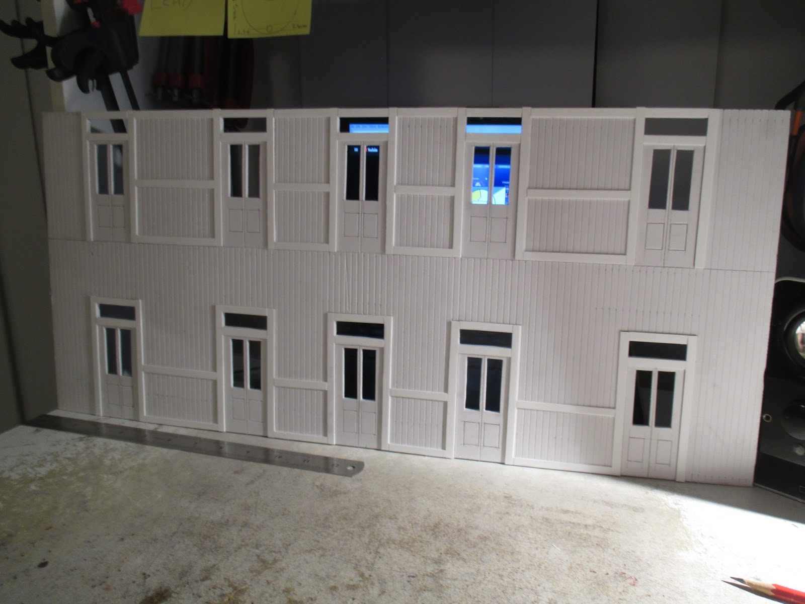
It's tricky to photograph this stuff sometimes. All scribing on this larger of the two front panels is done. The process was repeated on the shorter front wall, before moving on.

A knife was used to bevel the ends of the wall panels, making for a crude "mitre joint". This will allow the very edges of the walls to go together a little more seamlessly, than if I just butted the walls together
I'm really not sure this was necessary, as I've always intended to cover the outside faces of the joints with styrene corner trim, anyway. This will also make it more difficult to glue the walls together.

It's also all to easy to cut too deep and affect the nice straight edge of the wall.
As usual, taking it slow will give a reasonable result, as shown.

29/03/19
There's external frame-work all over the front faces of the building, and these are to be ame of ¼" wide strips of 1mm styrene.
I first cut a ¼" strip and marked it as the master, or pattern. Then, butting the styrene sheet, and the master against the piece of aluminium angle, the styrene was marked with a sharp pencil.
The strip is then cut off in the usual manner.

Cutting the styrene leaves a small raised ridge along the edge, on both the strip and the larger sheet from which it was cut. The knife is used to scrape this off. This is the most tedious and difficult part of mass-producing strips, in my book.

After cutting a single door-frame upright, it was marked as a master pattern. Then the rest of the uprights were cut to length, using the master as a pattern.
When I had enough uprights, they were glued onto the foamboard with superglue, taking care to align them properly with the frames scribed around the doors.

Because the uprights were positioned entirely by eye against the scribing, the exact length of the horizontal frame pieces will very slightly vary. So I'd lay the strip in place, and mark it with the sharpened pencil.
Cut to length, and sand with an emery board if it's slightly too long. I sometimes cut it a fraction of a millimeter too short, so I test it's fit on other doorways until I find one where it'll fit better.

The remaining framework was done in the same manner. The door-frame uprights still need minor trimming off the edges of the wall section. The framework is missing from the ends of the wall, as I'm waiting on some 4mm ABS angle to arrive, which will be fitted first as the corner bracing.
01/04/19
The short wall was done simultaneously.

The end walls were cut out, and scribed for horizontal weatherboards. I don't have any photos of the sides or rear of the Royal George, but I've a photo of the similar Club Hotel over the road, and it's end walls are horizontal boards with no external bracing.
After several years of searching for an affordable source of G-scale windows (including looking into casting them in lead), I remembered people build doll's houses in 1:24 scale, and looked into that market.
In short order, I found a supplier in Britain called Maple Street, and bought a small village's worth of moulded plastic windows and doors for just under $100, including shipping!
I traced around the windows in pencil, and cut them out. The handy thing about moulded or cast windows is that they cover up the edges of the hole in the wall, making things quicker and easier. These windows worked out about $3.50AUD each.

09/04/19
It suddenly occurred to me, that I never distressed any of these parts to look like timber.
The styrene fascia was an easy job to distress.
A section of blunt hacksaw blade was dragged along the length of the "boards" to make a rough grain effect. Some coarse emery tape was then used to give a finer grain appearance, and blend the much coarser hacksaw "grain" into the surface.
A light sanding with 400 grit sandpaper removed the remaining styrene "fuzz".

I then used a triangular needle file to cut tiny grooves into the ends of the "boards". The ends were then roughed up a little with the emery tape. The overall result is a huge improvement, and should look very good once painted.

The foamboard wall panels will be more difficult. I wish I'd have thought to do this before I'd glued the styrene bracing on.
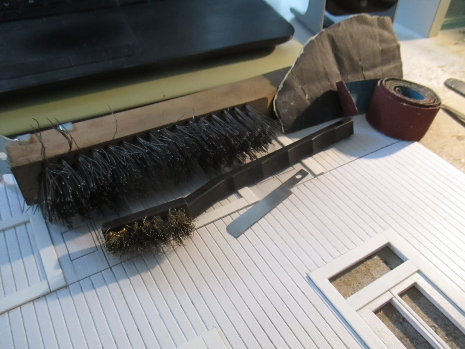
The large wire brush is excellent for distressing the foamboard, and the small brass brush gives a finer-looking grain to the doors. The styrene bracing is handled in the same manner as the fascia.

The effect is quite visible, but very difficult to photograph. It should show up better after the eventual coat of primer. The small wire brush is used for the doors, to give a finer grain appearance than the walls.

On the last railway, all lighting was self-contained in each building, running on rechargeable cells. Having to make sure all the buildings' batteries are charged before setting up for a run, just adds to the list of dis-incentives to actually run anything.
So next time, most if not all lighting, will be on a grid network, buried a few inches underground. Due to the higher number of buildings and the potential size of wiring network, I must concede that LEDs would be better suited to the task, than my preferred incandescent bulbs.

It suddenly occurred to me, that I never distressed any of these parts to look like timber.
The styrene fascia was an easy job to distress.
A section of blunt hacksaw blade was dragged along the length of the "boards" to make a rough grain effect. Some coarse emery tape was then used to give a finer grain appearance, and blend the much coarser hacksaw "grain" into the surface.
A light sanding with 400 grit sandpaper removed the remaining styrene "fuzz".

I then used a triangular needle file to cut tiny grooves into the ends of the "boards". The ends were then roughed up a little with the emery tape. The overall result is a huge improvement, and should look very good once painted.

The foamboard wall panels will be more difficult. I wish I'd have thought to do this before I'd glued the styrene bracing on.
The large wire brush is excellent for distressing the foamboard, and the small brass brush gives a finer-looking grain to the doors. The styrene bracing is handled in the same manner as the fascia.
The effect is quite visible, but very difficult to photograph. It should show up better after the eventual coat of primer. The small wire brush is used for the doors, to give a finer grain appearance than the walls.

Again in Microsoft Paint, I drew up another preschool-level drawing to re-explain to myself, how I'll handle the lighting of my structures in future. Because a goldfish has better memory than I do.
On the last railway, all lighting was self-contained in each building, running on rechargeable cells. Having to make sure all the buildings' batteries are charged before setting up for a run, just adds to the list of dis-incentives to actually run anything.
So next time, most if not all lighting, will be on a grid network, buried a few inches underground. Due to the higher number of buildings and the potential size of wiring network, I must concede that LEDs would be better suited to the task, than my preferred incandescent bulbs.

Bunnings now had corflute back in stock, so I could get on with making the floor and rear walls.
Like the walls, this had to be cut out on the balcony.
I expect I'll be spending a lot of time working on this thing on the floor or balcony; The latter is where the pub will be stored after it's done. No space for it indoors.
The lighting connection recess was a quick job to make, glued together with KS Bond, and tacked with superglue.

10/04/19
Some ½" wide PVC angle was bought and cut into 1½" long "brackets" to help hold the walls together. This stuff is a moulding, available in a number of shapes, to cover the joints between sheets of plasterboard. (also known as drywall, sheet rock, etc)
At $4 for eight feet, I think I'll be using a fair bit of this stuff for buildings..
The one issue with this stuff, is it's not made to a 90° angle, rather, it's about 85°. But I guess that's to be expected of something made to hide joints in plasterboard. I can correct the angle of these smaller pieces by squeezing them in the vice, but longer bits have to be used as-is.

Some 6mm square ABS tube arrived today, and has been cut to 10" lengths, then distressed and tidied up. They'll be the posts along the front of the pub.

The little sections of angle were glued to the base of the walls..

..Which made it far easier to position the walls accurately on the base.

To ensure the front walls are parallel with the edges of the base, the width of the verandah was marked every 6" or so. The walls were then carefully positioned on top of the marks.

11/04/19
Out on the balcony again, for easier photography. All bar one of the main wall sections have been glued in place. Some more bracing to hold the front walls in place, then I can measure the gap in the middle, and make the missing section to fit.

The joint between the front and end walls isn't perfect, but it'll be covered with ABS angle when it arrives..

Although the edges of each wall panel were glued before assembly, (along with the angle) a bead of glue was laid over all the joints, inside the structure, to ensure a good bond and to make the joints watertight.

12/04/19
The corners were stiffened up with offcuts of corflute cut into triangles. The 90 degree corner of each triangle was cut out, to allow these braces to be fitted over the angle brackets. A drop of superglue here and there helps tack the braces in place until the KS Bond contact cement sets.

Having bought some more PVC angle, I set about stiffening the tops of the walls. The angle was cut out to clear the fanlights, glue applied to both surfaces, left to sit for a minute, and clamped together for ten minutes. Again, tacking with superglue allows the clamps to be removed sooner, so the process can be repeated on the other wall.

The rear walls were then braced to the front walls, using a try square to make sure the front walls are perfectly vertical. The resulting assembly is surprisingly rigid. I can now measure the gap in the front walls, and make the remaining section to fit.

17/04/19
Weirdly enough, an offcut of foamboard was a perfect fit for the corner section.

The top door is the same as those along the fronts, with the bottom door being made a bit wider as per my references.
The joints of the walls were covered with the ¼" strips, taking a lot of care to ensure it all aligned nicely. The horizontal external framework was then cut to fit.

Some PVC angle was partially flattened out in the mini vice, to match the angle of the wall joints.
I can't use KS Bond along the walls' vertical joints, as the solvents in the glue would distort the styrene strips covering the joints on the outside; Superglue was run down the vertical joints from behind.

24/04/19
Preparing to make the verandah/fascia structure. Back to the painstaking job of scribing and distressing styrene. I hate this bit, best to push through and move on. Notches were cut out for the posts, using the fascia as a guide for spacing and dimensions.
The lower deck sections were glued on with epoxy for a dependable bond, with superglue to help prevent the styrene floors from bowing up while the epoxy sets. Even so, the floor sections were weighed down with a piece of timber for at least six hours.

I fucked up here. I should've made the fascia and resultant post spacing to match the width of the corner verandah floors, rather than spacing it all based on the wall dimensions. The floor at the corner is much too wide, and will be cut down to match the styrene floor sections as used along the fronts.

25/04/19
Having glued two posts to the fascia, the fit in the floor's notches is tested before proceeding further. No problems.

Each post was aligned by eye, with the triangular cut-out on the fascia. Then, measured against the previously-fitted post, to ensure the current post is as close to perfectly-vertical as I can get it. Being careful not to let it move, the post is then stuck to the fascia with superglue.
I don't like using plastics cements in plastic fabrication, due to them being solvent-based, melting the plastic to "weld" the pieces together. As the solvent evaporates and the gooey plastic re-solidifies, it shrinks, causing often irreparable distortion in the entire assembly. The joints themselves are very good, but the risk of distortion is often too great. I think superglue has a very mild solvent-welding effect, but not enough to cause distortion, in my experience. I think this mild welding effect helps make up for the generally-low strength of cyanoacrylates.

A piece of aluminium angle was clamped to the bench to ensure the posts are all vertically-positioned correctly. Lengths of PVC angle are cut to fit between the posts. They're made to a snug push fit, to hold the fascia straight, instead of bowing outwards. After gluing, the whole assembly is quite rigid.

27/04/19
The floor around the front corner is fitted. I'm hoping the joint lines will blend in better once it's all painted..
Note the post notches in the front corners of the floor - I would've preferred a single post in each corner, with the remaining posts equidistantly positioned. It was my mistake in designing the front corner floor that's caused this, and with the fascias already made, I'll have to live with this post spacing. Not quite what I wanted, but there's plenty of structures built like this anyway..

The fascias need shortening a little to fit the cut-down front corner. A "splint" of 3mm x 25mm aluminium bar was cut and roughened up with emery tape. Epoxy and clamping the assembly to the bench resulted in a strong, straight joint. The process was repeated on the other fascia section the following day.

28/04/19
A long-awaited shipment of 4mm ABS angle has arrived, so the corners of the building can finally be finished. The angle was stuck on with thick superglue.

Unsurprisingly, I forgot to distress the angle before fitting, so it had to be done in-situ.

The short front wall, as it turns out, wasn't quite straight when I glued it to the base. It's slightly wavy at the bottom, which I never noticed until I'd fitted the bottom floor. It's actually far worse than the camera makes it look..

I can't reposition the wall, so the gaps have to be filled with strips of styrene. I always knew that all the ground floor doorways would need filling in, and this was done with some 1.5mm wide half-round strip, left over from the cab beading on my Malcolm Moore loco. It was placed in upside-down, which helped hold it in place over the gap while applying superglue.


I do wish I'd have used foamboard for the floor/base. It would've been much more durable than this corflute, despite using up a lot of fairly-expensive material. In any case, the front and side edges need covering with plastic angle, distressed to look like timber.

Epoxy for (hopefully) long-term durability was used, and the sections clamped for a few hours. Fine-tipped applications of superglue were made just under the front edge of the styrene floor to reinforce it all.

29/04/19
The top verandah floor sections need to be held straight, so some 3mm x 12mm aluminium bar was bought. Like the aforementioned fascia splints, the bar was roughened up and attached with epoxy, tacked with superglue.


Glue set, the pub was turned on it's side, on the bench, then fasica and floor assemblies were test-fitted. A couple of very minor adjustments, and the fit was good. The width of the angle was marked on the wall..

..So when I applied the KS Bond contact cement, I wouldn't spread it anywhere outside the area the angle will mount. Now the scary part begins. I've only one shot at this, and have to work quickly..

Some thick superglue was applied to the bottom floor cutouts, where the posts will seat into. Then, the top floor was placed, and the contact cement stopped it falling over while I positioned the fascia/post assembly. Once those were in place, I could start gluing the top floor to the fasica assembly.
A small (2" square) scrap of rag is great for quickly wiping and soaking up excess superglue before it dries on the surface. I consider it an essential when supergluing. Once it gets too soaked with rigid dried glue, it's binned and replaced.

After letting the whole thing sit for an hour, I can turn the building over and apply more glues to areas I couldn't reach before.
The 85° angle of the, well, angle, means the surface contact area between wall and angle is quite small. So the gap here was filled with more KS Bond.

After letting that sit for a while, I could turn the thing over again. I then stepped back, let the glue set overnight, and looked for any problems before going any further.

I noticed the afternoon sun was glowing through some spots in the styrene external framing, where it covers the joints in the foamboard walls. A couple quick coats of black aerosol paint had this sorted.

12/05/19
Fitted the other verandah assembly, along with the ends of the fasica.


The fasica end sections were constructed and fitted in the same manner as the fronts.

The ½" aluminium bar was epoxied in place. The gap will be measured and the remaining verandah/fasica section made to fit.

The building is stored on my balcony, most days. Whenever I bring it inside to work on, I find numerous ants scurrying all over it. I suspect they're making a nest in the corflute - another reason I should've used foamboard for the floor. In any case, I've sealed up most of the corflute holes with KS Bond.
The unsealed flutes have had liquid ant poison dribbled inside. The ants are attracted to the sweet smell/taste of the poison, and transport it back to their nest(s). The other ants then eat it, effectively exterminating the nest. I'll wait a week or two, then seal up the remaining flutes.

14/05/19
A crude jig has been made from the "sprues" of a laser-cut wooden coach kit I'm building.
It's to consistently cut 7.9mm square styrene tube into ½" lengths.

After distressing.
The 7.9mm tube is a close fit over the 6mm verandah posts. These ½" lengths will bring the post ends up to the right height, and functions as part of the ornate top ends.

Before I can even measure the front corner for the missing verandah/fasica sections, I need to fit the corner posts. I found the front corner post here wouldn't fit, due to the 1" aluminium bracing bar being too long and protruding 3mm into where the post goes.
The dremel was used to slowly grind away the excess metal. This quickly caused the aluminium to heat up, so frequent stops were needed to make sure the bar didn't get hot enough, to affect the fasica to which it's glued. Small G-clamps were fitted once the bar got hot, to help hasten it's cooling.
After some further minor fettling, the corner posts were glued in.

16/05/19
After carefully making them to fit snugly, the PVC angle stiffeners were glued into place, and the top verandah floor made/fitted. Beads of epoxy and superglue were ran side-by-side; The floor was then pushed into place, and held in place for twenty seconds until the superglue set.

Front section made/fitted, and the verandah/fasica structure is all but complete.

At this point, I felt it was time for a coat of primer. A clean 3" brush was used to remove any dust and debris.

I think "El-cheapo" Australian Export brand grey primer should be fine. Surprisingly good stuff for $4.50 a can. The very fine spray nozzle allows me to paint all the surfaces of the verandah structure, without any runs or thick spots whatsoever.
The topcoat colours will all be outdoor-grade, UV-stabilised stuff, possibly sealed with a UV polyurethane. The paint might wait until the roof structure is done, though - not yet sure on that..

One coat was mostly sufficient, but I may yet recoat the more lightly-coated spots. Will leave this to harden for a few days while I work on other things..

Much earlier in the build, I'd used a program called "GIMP" to colourise one of my reference photos. This was to help me decide on a livery before it might affect the process of assembly. I'd like to include the colourised image in this write-up, but what with copyright etc. it's probably more trouble than it's worth.
After changing out the nozzle for a finer-spraying Export one, the first coat of cream was applied.
The paint used was Dulux Metalshield's "Sandbank". About $11 from Bunnings.
I figure the stuff should do fine on plastic, and we use that range almost exclusively at ANGRMS, on locos/rollingstock stored outdoors. So it should hold up nicely for this.
Although supposedly "semi-gloss", it's come up a very nice flat finish.
I've only masked a small spot at the top front corner of the building, as I'm not yet certain how the verandah roof will attach. I won't know that until a long-overdue shipment of more 6mm square tube arrives..

It's left a lot of dry powdery overspray around. Most of it can be brushed away prior to further painting..

I'd anticipated problems with over-applying the paint under the verandah, but with the Export nozzle, it went pretty well. Two coats, two hours apart, had the cream paint done - mostly.

24/05/19
Many of the poles' backsides couldn't be reached by spraying; So some paint was sprayed into the lid, a little thinner mixed in, and the job finished with a brush.

27/05/19
Yesterday, after letting the cream paint dry, I tried brush painting some doors and the bottom section of the front walls. Gloss Mission Brown, of the aforementioned range was used. That was more of an experiment, as I didn't fancy spending several hours, carefully masking to spray it. The finish wasn't very good at all, so that was left to dry overnight. I'll mask it off, and spray the brown.
Today, the posts are marked out so they can be masked. A pencil mark was made on the front of each post, 55mm from the floor, to match the wall behind.

Tamiya's excellent masking tape was used here for a sharp edge. Some care was needed to ensure the tape was applied squarely around the pole. Painting the bottom section of the walls and posts a dark colour, will help disguise the dirt and muck that will inevitably splash up from the rain.
Funnily enough, the Royal George was in fact painted this way in the 1950s.

2½ hours later, this thing is finally masked and ready to paint.
There's a lot of overspray on my cheap little outdoor table, but it's great not having to worry about overspray for once. A wipe with enamel thinners on a rag won't harm the glass and powdercoat..

First coat of mission brown. I should've put the better nozzle on it, as it's a little thick in places. A second coat with the good nozzle fitted, should see this done. Some flat clear UV-resistant polyurethane will remedy the gloss, but that's a ways down the line..

29/05/19
I knew I'd forgotten something. Turns out that was to buy a roll of low-tack masking tape.
Soaking the tape with the garden hose, helped in allowing the tape to come off, without taking the paintwork with it. Even so, there's a lot of touching up to do.. Now that I think of it, I was also supposed to rub a scotchbrite pad over every surface prior to applying the colour coats. Would've likely had a lot less peeling..

30/05/19
The cut edges of the foamboard are porous, and will take far too many coats of paint (and time) to colour. Thin superglue was applied to these surfaces, and the excess wiped off with a finger. Seals the foamboard quite well. The downside is a thick coating of dried superglue on my finger..

The pub's upside down, so the top surfaces of the door and fanlight cutouts could be painted. I was originally going to paint the door frames white, but decided that would probably be too garish. I think they look better in brown.

31/05/19
Even after two sprayed coats obscuring most of the wood grain detail, much of the brown (the posts in particular) needed touching up with a brush. Most of the of the posts' backsides couldn't be sprayed, so they were brushed.

18/06/19
During another round of touchup, I noticed the bottom of this post is in the wrong place.
It's pretty bad, to my eye. But it's not really worth the trouble to fix, and it's not appallingly noticeable. I'll try and live with it.

No comments:
Post a Comment